Delay-adjustable breaker

A technology for circuit breakers and adjusting parts, applied in the direction of adjusting protection switch conditions, protection switch operation/release mechanism, etc., can solve problems such as unfavorable processing, small adjustment stroke, limited axial adjustment stroke, etc., to achieve convenient processing and assembly, increase Accuracy, the effect of increasing the adjustment stroke

Active Publication Date: 2014-11-12
CHINT GROUP CORPORATION +1
View PDF4 Cites 2 Cited by
  • Summary
  • Abstract
  • Description
  • Claims
  • Application Information

AI Technical Summary

Problems solved by technology

However, because the circuit breaker still directly adjusts the axial movement of the drawbar through the adjustment device to achieve the adjustment purpose; therefore, the axial adjustment stroke caused by directly moving the drawbar is limited, basically only about 5mm, and the adjustment stroke is small, resulting in low adjustment accuracy. , and due to the limitation of the bracket for fixing the drawbar on the tripping mechanism, the electromagnetic release and the structure of the shell, the axial movement of the drawbar and the matching part of the shell cannot be equipped with an interphase insulation isolation device, which has certain potential safety hazards
In addition, in addition to the separation and closing of the drawing rod processing mold in the X-axis direction, core pulling needs to be set in the Y-axis and Z-axis directions. Too complicated molds are not conducive to processing, and the processing cost is high.

Method used


Image

  • Delay-adjustable breaker
  • Delay-adjustable breaker
  • Delay-adjustable breaker

Examples


no. 1 approach

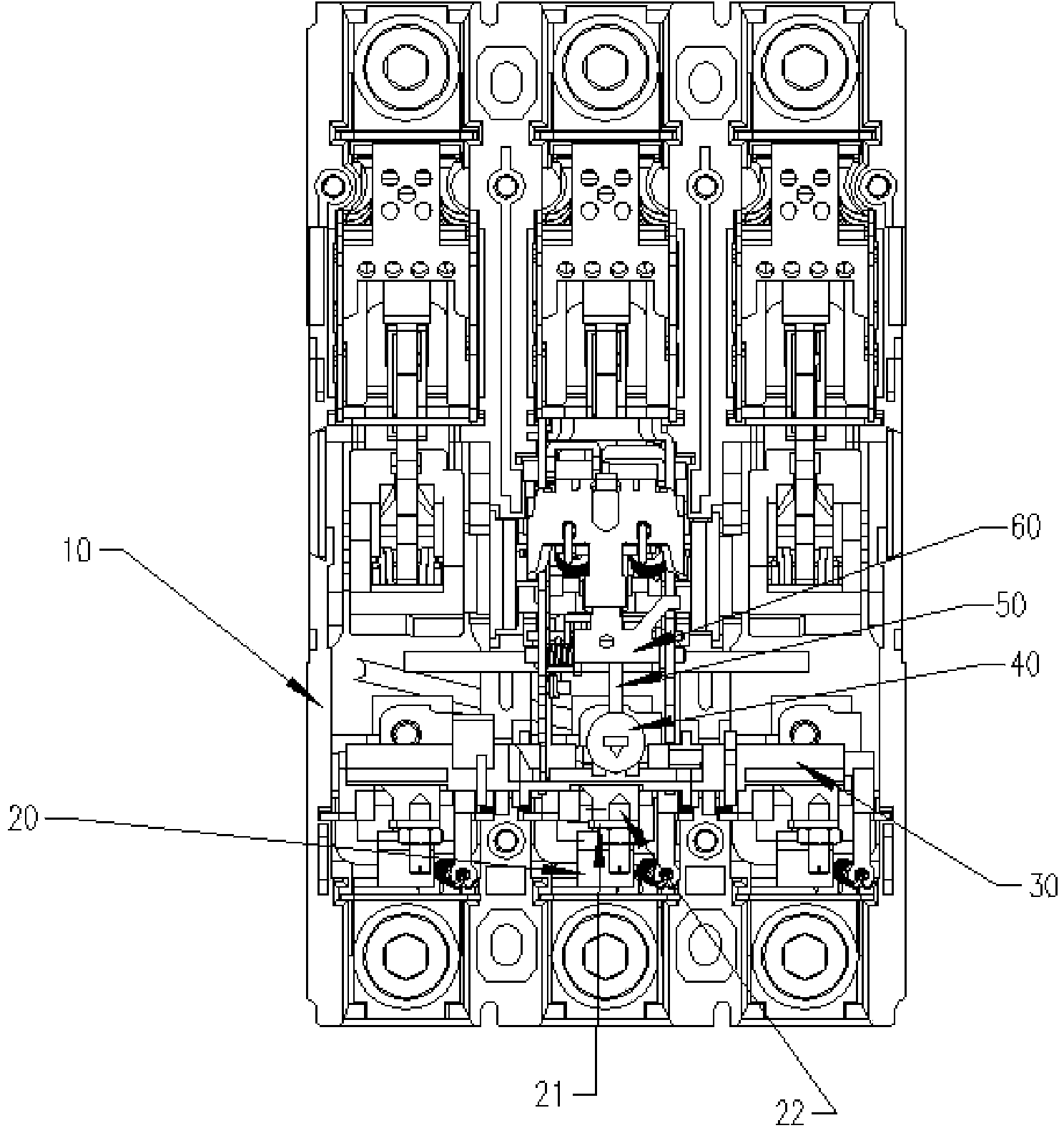
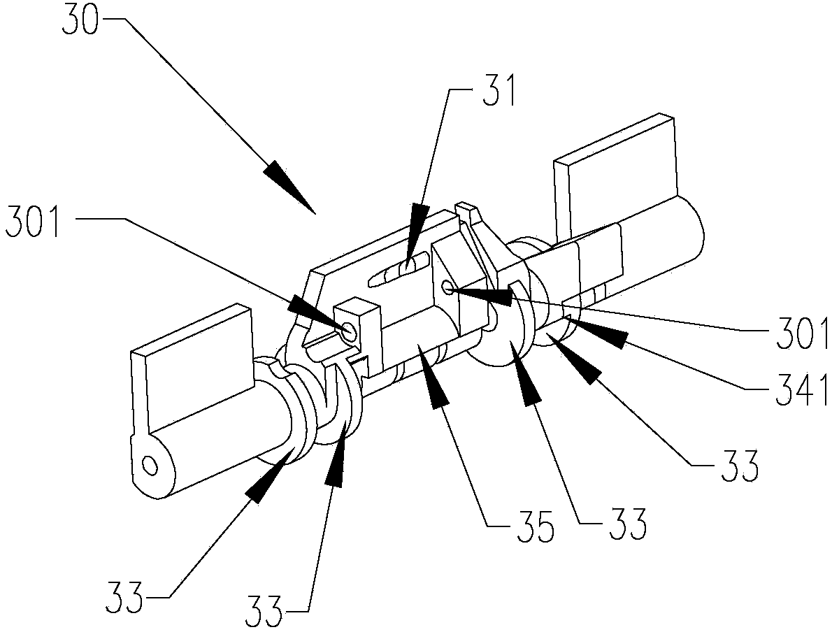
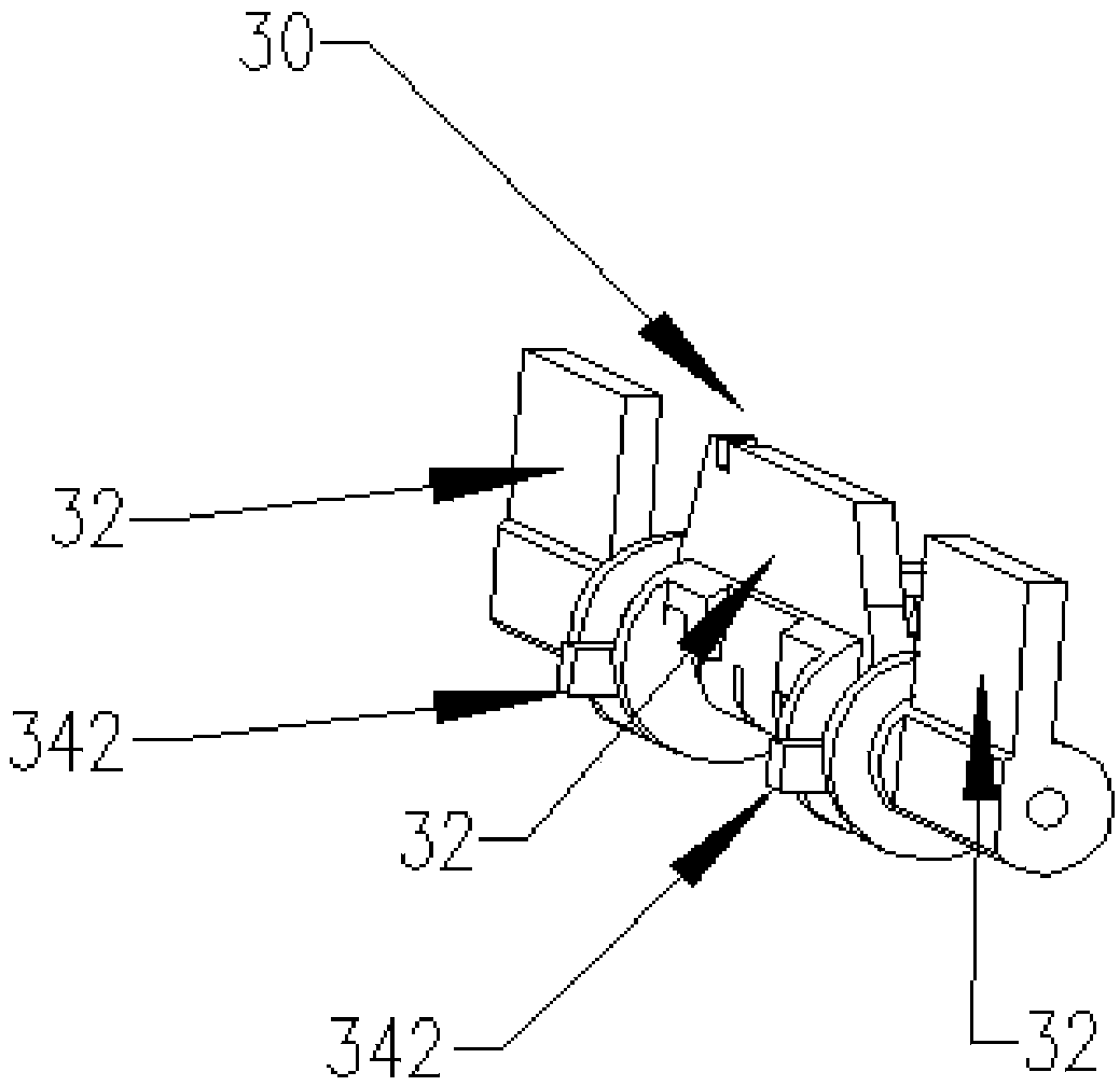
[0040] see Figure 1-8 To illustrate the first embodiment of the present invention, the transmission member 30 is referred to figure 2 , 3 In the first embodiment shown, in addition to the plane 32 matched with the trigger member 22, the transmission member 30 also includes a transmission surface 31 and a positioning surface 35, so that the transmission member 30 can only be within a limited angle range Rotating limiting surface 342 (see image 3 ) and limit surface 341 (see figure 2 ) and the opposite phase-to-phase insulation isolation 33. Such as Figure 5 , 6 As shown, the adjustment member 50 is installed on the transmission member 30 through the rotation hole 56, and the adjustment member 50 also includes an arc surface 53 matched with the positioning surface 35, and it is positioned on the transmission member 30 through the arc surface 53 on it. On the positioning surface 35 on. Regulator 50 also includes a trip lever 61 (see Figure 6 ) corresponds to the tri...

no. 2 approach

[0042] see Figure 1-4 , 7-10 illustrate the second embodiment of the present invention, the adjustment member 50 is as Figure 9 As shown, in this embodiment, in addition to being provided with an adjustment slot 51 that matches the adjustment rod 43 of the rotation adjustment device 40 and an adjustment surface 52 that cooperates with the transmission surface 31, the adjustment member 50 is also provided with a tripping device 60. The trigger part 54 is mechanically matched with the trip lever 61 on the top. Different from the first embodiment, the adjustment member 50 is not provided with an arc surface 53 matching with the positioning surface 35 , but a limiting step 55 for defining the positioning spring 70 is further preferably provided.

[0043] The installation relationship between the adjustment member 50, the transmission member 30 and the tripping device 60 is as follows: Figure 10 As shown, the adjusting member 50 is axially movably mounted on the shaft 80 of th...

no. 3 approach

[0045] see figure 1 , 3 , 4, 7, 8, 11-13 illustrate the third embodiment of the present invention, in this embodiment, the transmission member 30 is provided with a transmission surface 31 (see Figure 12 ), and the transmission member 30 is provided with a limit surface 342 (see image 3 ), a finite plane 341 is also set (see Figure 12 ), so that the transmission member 30 can only rotate within a limited angle range. The tripping device 60 is provided with a tripping lever 61 and a triggered part 62 which mechanically cooperates with the regulating surface 542 on the triggering part 54 (see Figure 13 ). Regulator 50 (see Figure 11 ) in addition to being provided with an adjustment groove 51 matched with the adjustment rod 43, a rotation hole 56, an adjustment surface 52 matched with the transmission surface 31, and a limiting step 55 defining the positioning spring 70, it also includes such as Figure 13 The adjustment surface 542 on the trigger part 54 that is matc...


PUM


Abstract

The invention discloses a delay-adjustable breaker which comprises a transmission piece, a rotating adjustment device, a releasing device, thermomagnetic systems with adjustable triggering pieces and an adjustment piece. The adjustment piece can rotate through a rotating hole and is installed on the transmission piece in a linearly-moved mode. An adjustment groove of the adjustment piece is mechanically coupled with an adjustment rod of the rotating adjustment device, an adjustment face of the adjustment piece is mechanically coupled with a transmission face on the transmission piece, and a trigger part of the adjustment piece is mechanically coupled with a releasing rod or a triggered piece on the releasing device. A first distance adjustment mechanism is arranged between the adjustment face of the adjustment piece and the transmission face of the transmission piece, and / or a second distance adjustment mechanism is arranged between the trigger part of the adjustment piece and the releasing rod or the triggered piece of the releasing device, so that the effective distance for adjusting a current setting value is achieved through the first distance and / or the second distance along with axial movement of the adjustment piece. Adjustment is accordingly not influenced by structures of the mechanisms and a shell any more, the adjustment stroke is large, and the delay-adjustable breaker is simple in structural design, convenient to manufacture and stable in working performance.

Description

technical field [0001] The invention relates to a plastic case circuit breaker, in particular to a circuit breaker with adjustable overload setting value delay. Background technique [0002] A circuit breaker with adjustable overload setting generally includes a housing, an overload setting system, and a tripping mechanism with a drawbar; both the overload setting system and the tripping mechanism with a drawbar are fixed on the housing. The overload setting value of the circuit breaker is determined by the distance between the adjusting screw on the overload setting system and the drawbar, and the distance between the trigger surface on the drawbar and the triggered part on the tripping mechanism. The distance is proportional to the setting value. related to. The adjustment accuracy and performance stability of the current circuit breaker with adjustable overload setting value are often not up to standard, and it is difficult to process, manufacture and adjust, and the pro...

Claims


Application Information

Patent Timeline
IPC IPC(8): H01H71/44H01H71/74
Inventor 江华华
Owner CHINT GROUP CORPORATION
Why Eureka
Try Eureka