Sheet punching device and punching method thereof

A technology for thin plates to be processed, which is applied in metal processing equipment, drilling/drilling equipment, manufacturing tools, etc. It can solve the problems of inability to adjust the processing size and low processing accuracy according to needs, and achieve shortened processing cycle and high precision. High, avoid deformation or fracture effect

Inactive Publication Date: 2014-07-02
ZHEJIANG GEELY POWERTRAIN CO LTD
View PDF4 Cites 1 Cited by
  • Summary
  • Abstract
  • Description
  • Claims
  • Application Information

AI Technical Summary

Problems solved by technology

[0006] The present invention is mainly aimed at the problems that the existing hole cutter can only process a fixed size, when processing holes of different sizes, the hole cutter of the corresponding size needs to be replaced, the size of the processing size cannot be adjusted according to the needs, and the processing accuracy is low. , to provide a thin-plate hole-drilling device and a hole-drilling method thereof capable of adjusting the processing size according to processing needs, cutting holes of different sizes without changing tools, saving processing time, simple operation, no need for secondary processing, and high processing accuracy

Method used


Image

  • Sheet punching device and punching method thereof
  • Sheet punching device and punching method thereof
  • Sheet punching device and punching method thereof

Examples


Embodiment 1

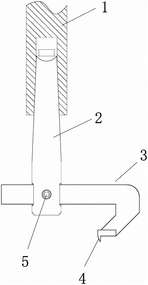
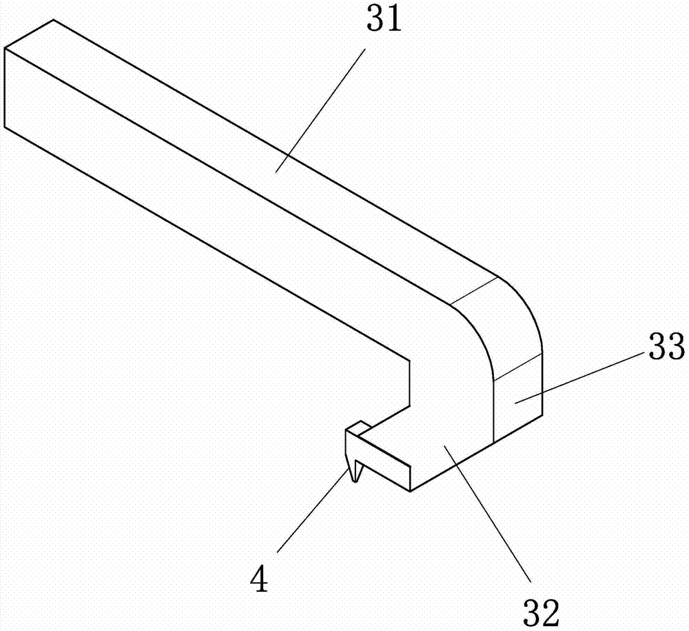
[0027] Embodiment 1: as figure 1 , 2 As shown, a thin plate hole opening device includes a tool bar 2 connected to a drill press. The tool bar 2 is inserted into a rotating sleeve 1 of the drilling machine. The rotation of the rotating sleeve 1 of the drilling machine can drive the tool bar 2 to rotate. A knife holder bar 3 runs through the lower end of the knife bar 2 , and the knife holder bar 3 includes a connecting arm 31 and a fixed arm 32 , and the lower end of the fixed arm 32 is fixed with a blade 4 . The fixed arm 32 is connected to the connecting arm 31 through the transition arm 33, the angle between the transition arm 33 and the connecting arm 31 is a right angle, and the angle between the transition arm 33 and the fixed arm 32 is an obtuse angle, that is, the space angle between the fixed arm 32 and the connecting arm 31 is an acute angle. The connecting arm 31 radially penetrates the lower end of the tool bar 2 and is fixed by the locking post 5. The locking po...

Embodiment 2

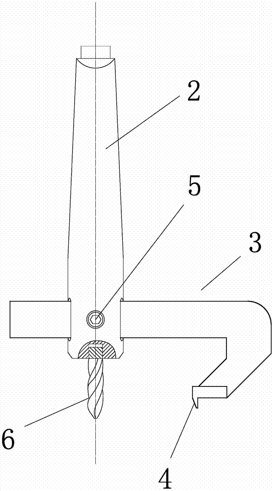
[0030] Embodiment 2: The structure of this embodiment is basically the same as that of Embodiment 1, the difference is that, as image 3 As shown, the lower end surface of the cutter bar 2 is plugged with a positioning drill bit 6 , and the positioning drill bit 6 is coaxial with the cutter bar 2 . The vertical distance from the lowermost end of the positioning drill bit 6 to the lower end surface of the cutter bar is greater than or equal to the vertical distance from the lowermost end of the blade 4 to the lower end surface of the cutter bar. The difference between the vertical distance from the lowermost end of the positioning drill 6 to the lower end surface of the cutter bar and the vertical distance from the lowermost end of the blade 4 to the lower end surface of the cutter bar is smaller than the thickness of the thin plate 10 to be processed.

[0031] The lower end surface of the cutter bar is provided with a positioning drill bit, and the extension length of the posi...

Embodiment 3

[0033] Embodiment 3: The structure of this embodiment is basically the same as that of Embodiment 1 or 2, the difference is that, as Figure 6 , 7 As shown, there is a drip hole 312 on the lower end surface of the connecting arm 31. The drip hole 312 is vertically corresponding to the blade 4. There is a perforation 311 at the axis of the connecting arm 31. The perforation 311 communicates with the drip hole 312. The perforation 311 runs through an infusion soft tube. Pipe 7, one end of the infusion hose 7 extends to the drip hole 312, and the other end is connected with the water source 9, the water source 9 is a water bag, the water source 9 surrounds the outer surface of the rotating shaft sleeve 1 fixed on the drilling machine, and the infusion hose 7 is equipped with Water volume control valve 8 that controls water flow by squeezing the infusion hose.

[0034] During the cutting process of the blade, open the water control valve, so that the cooling water of the water so...


PUM


Abstract

The invention relates to sheet punching, in particular to a sheet punching device and a punching method of the sheet punching device. The sheet punching device comprises a cutter bar connected with a drilling machine, wherein the lower end of the cutter bar penetrates through a cutter frame bar, the cutter frame bar comprises a connecting arm and a fixing arm, the connecting arm penetrates through the lower end of the cutter bar in the radial direction and is fixed to the lower end of the cutter bar through a locking pillar, an included angle in the vertical plane is formed between the fixing arm and the connecting arm, and a blade is fixed to the lower end of the fixing arm. The sheet punching device has the advantages of being capable of adjusting machining sizes according to machining needs, not needing to replace cutters when machining holes of different sizes, saving machining time, being simple to operate, not needing secondary machining, being high in machining accuracy and the like.

Description

technical field [0001] The invention relates to a thin plate hole drilling process, in particular to a thin plate hole drilling device and a hole drilling method thereof. Background technique [0002] In the existing type of perforating knife, two cutting edges are arranged on the edge of the cylindrical cutter bar, and the two cutting edges are respectively located at the radial ends of the cutter bar. . There is also a type of perforating knife with multiple cutting edges arranged on the edge of the cylindrical cutter bar. The multiple cutting edges are evenly arranged around the axis of the cutter bar. When the cutter bar rotates, all the blades can rotate around the axis of the cutter bar for cutting. However, the blades of these two types of perforating knives are fixed with the tool holder, and even form an integrated structure. The radius of rotation of the blade cannot be adjusted, that is, one perforating knife can only process a fixed size, and it needs to be repl...

Claims


Application Information

Patent Timeline
Patent Type & Authority Applications(China)
IPC IPC(8): B23B51/05
CPCB23B51/05
Inventor 黄财明刘晓庆宋文平孙艳陈杰王瑞平
Owner ZHEJIANG GEELY POWERTRAIN CO LTD
Why Eureka
Try Eureka