Supercharge Your Innovation With Domain-Expert AI Agents!

Automatic bouncing structure for screw type electric coupler

An electrical connector and screw technology, which is applied in the field of automatic pop-up structure, can solve the problems of unfavorable miniaturization development of electrical connectors, increase in the lateral size of plastic bodies, restricting the expansion and application of electrical connectors, etc., and is conducive to the development of miniaturization. , Reduce the horizontal size, the effect of simple assembly operation

Active Publication Date: 2014-11-12
DINKLE M&E CHINA
View PDF5 Cites 0 Cited by
  • Summary
  • Abstract
  • Description
  • Claims
  • Application Information

AI Technical Summary

Problems solved by technology

However, the above-mentioned automatic spring-up structure of the screw usually sets the spring vertically on one side of the screw, see figure 1 , corresponding to the spring, a groove for accommodating the spring needs to be designed on the plastic body, resulting in an increase in the lateral size of the plastic body, which is not conducive to the miniaturization development of electrical connectors, thus restricting the expansion and application of electrical connectors

Method used


Image

  • Automatic bouncing structure for screw type electric coupler
  • Automatic bouncing structure for screw type electric coupler
  • Automatic bouncing structure for screw type electric coupler

Examples


Embodiment Construction

[0020] The preferred embodiments of the present invention will be described in detail below in conjunction with the accompanying drawings.

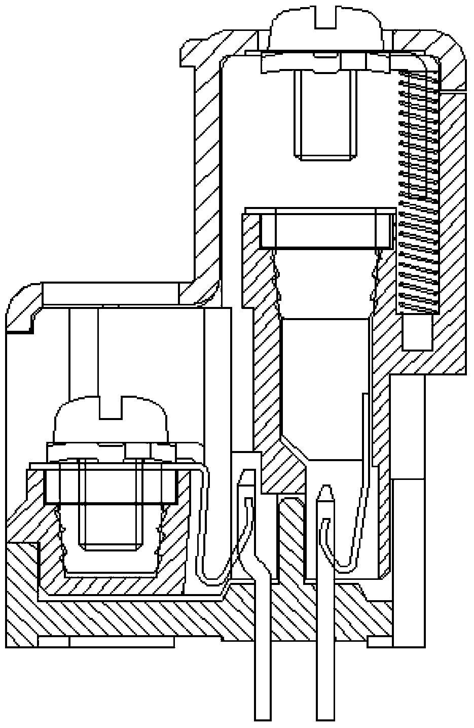
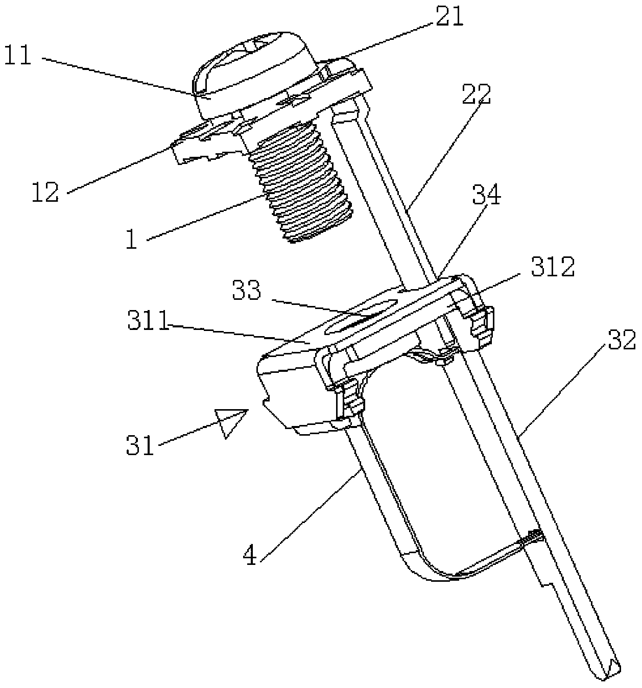
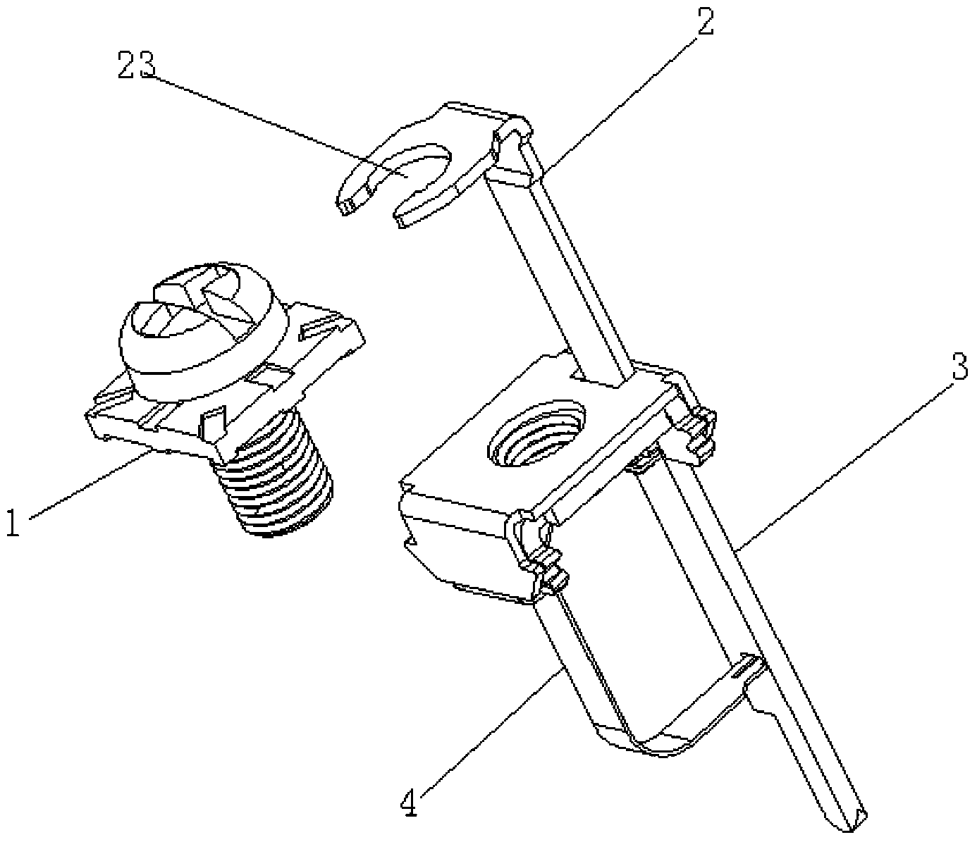
[0021] Such as figure 2 and image 3 As shown, an automatic pop-up structure of a screw 1 type electrical connector, based on the direction of use, includes a screw 1, a supporting terminal 2, an L-shaped conductive plate 3 and a spring piece 4.

[0022] The conductive plate 3 includes a flat plate portion 31 arranged horizontally and a foot portion 32 arranged vertically. The flat plate portion 31 is in the shape of a sheet, and the foot portion 32 is in the shape of a rod. One end of the foot portion 32 is fixedly connected to one side of the flat portion 31; The middle part of the part 31 is provided with a screw hole 33 matching the screw 1, and the side of the screw hole 33 close to the foot part 32 is provided with a first through hole 34; the screw 1 is located above the flat part 31 of the conductive plate 3, facing the screw ho...


PUM


Abstract

The invention discloses an automatic bouncing structure for a screw type electric coupler. The automatic bouncing structure for the screw type electric coupler comprises a screw, a supporting terminal, an L-shaped current-conducting plate and a spring sheet. The current-conducting plate comprises a flat plate part arranged horizontally and an outgoing pin part arranged vertically, the flat plate part is in a sheet shape, the outgoing pin part is in a bar shape, and one end of the outgoing pin part is fixedly connected to one side of the flat plate part. A screw hole matched with the screw is formed in the middle of the flat plate part, and a first through hole is formed in the side, close to the outgoing pin part, of the screw hole. The screw is located above the flat plate part and directly faces the screw hole. One end of the supporting terminal is fixedly connected with the screw in a detachable mode, and the other end of the supporting terminal penetrates through the first through hole and is fixedly connected with the spring sheet. The spring sheet is located below the flat plate part, and the supporting terminal can vertically compress the spring sheet to enable the screw to be connected with the screw hole. According to the automatic bouncing structure for the screw type electric coupler, the spring sheet is adopted to replace a spring used in the prior art to achieve automatic bouncing up of the screw, the transverse size of the plastic body of the electric coupler can be reduced effectively, and micromation development of the screw type electric coupler is promoted.

Description

technical field [0001] The invention relates to a screw-type electrical connector structure, in particular to an automatic spring-up structure of the screw-type electrical connector. Background technique [0002] Electrical connectors can quickly realize the connection between wires and wires, wires and circuit boards, and circuit boards and circuit boards. They are indispensable components in electronic equipment, and their application fields are becoming more and more extensive. Depending on the application object, frequency, power, application environment, etc., there are various electrical connectors with different structures. The connection methods between the electrical connector and the wire mainly include screw type, spring type, piercing the wire insulation, and cold-pressed terminals at the end of the wire. Screw-type electrical connectors usually use screws to quickly lock and connect wires. In the unlocked state of the screw-type electrical connection, in order...

Claims


Application Information

Patent Timeline
IPC IPC(8): H01R4/28H01R4/40
Inventor 吴上财
Owner DINKLE M&E CHINA
Features
  • R&D
  • Intellectual Property
  • Life Sciences
  • Materials
  • Tech Scout
  • Unparalleled Data Quality
  • Higher Quality Content
  • 60% Fewer Hallucinations
Learn More