Detachable handle of pot

A technology for pots and handles, applied in the directions of home utensils, kitchen utensils, applications, etc., can solve problems such as poor practicability, complex structure, shaking, etc., to reduce transportation and storage space, facilitate disassembly and installation processes, and achieve stability and stability. safety effect

Active Publication Date: 2014-11-19
ZHEJIANG AISHIDA ELECTRIC CO LTD +2
View PDF10 Cites 18 Cited by
  • Summary
  • Abstract
  • Description
  • Claims
  • Application Information

AI Technical Summary

Problems solved by technology

[0002] Cooking utensils for kitchen cooking, such as frying pans, usually include a pot body and a long handle fixedly connected to the side wall of the pot body. The long handle is generally fixed on the pot body and is not easy to disassemble. The volume is large, when the product is transported or stored, it needs to provide a large space to place the pot, and its transportation cost, storage cost and packaging cost are relatively high
[0003] The current detachable handles of pots are mostly complicated in structure, the disassembly and installation process of the handle is cumbersome, and the practicability is poor
In addition, because the components in the detachable structure of the handle are not tightly combined and firm enough, after a long period of use, the detachable structure of the handle will shake, and there is a risk of the pot falling during use

Method used


Image

  • Detachable handle of pot
  • Detachable handle of pot
  • Detachable handle of pot

Examples


Embodiment Construction

[0031] The present invention will be further described below in conjunction with the accompanying drawings and specific embodiments.

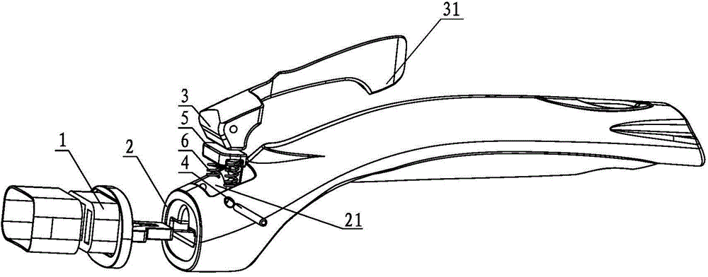
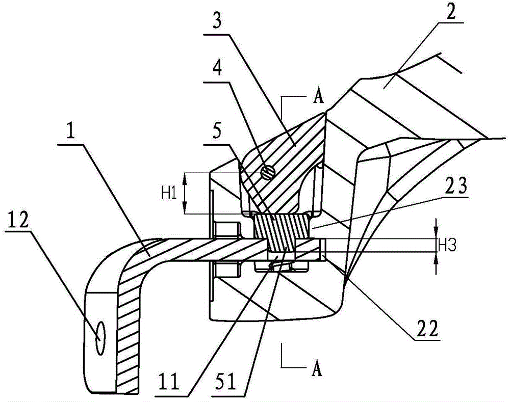
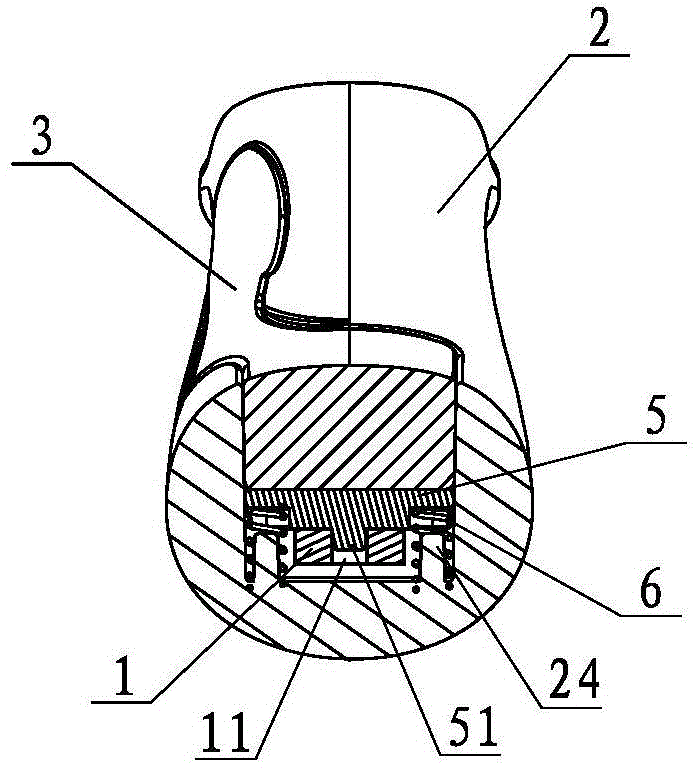
[0032] The handle for removing the pot as shown in the figure is composed of a pot body connector 1 and a handle 2 detachably connected with the pot body connector.

[0033] The handle body 2 is provided with a receiving groove 21, and the receiving groove 21 is used for placing the control rod 3 for disassembling or assembling between the connecting part of the pot body and the handle body. The head of the control rod 3 is in the shape of a cam, which is pivotally connected with the head of the handle body located on both sides of the receiving groove through the pin shaft 4 , so that the control rod 3 can rotate around the pin shaft 4 .

[0034] The rear end of the said pot body connector 1 is provided with a vertical positioning hole 11, and the bottom of the control rod 3 is provided with a locking piece 5 located in the receiving groove, a...


PUM


Abstract

The invention discloses a detachable handle of a pot. The conventional detachable handle of the pot is complicated in structure, tedious to detach and mount and poor in practicability. The detachable handle is characterized in that an accommodating groove is formed in a handle body and used for accommodating a control rod allowing detach or assemble of a pot connecting part and the handle body; the control rod with the head in a cam form is coupled with portions, on two sides of the accommodating groove, of the head of the handle body through a pin; the read end of the pot connecting part is provided with a longitudinal positioning hole, a locking part is arranged in the accommodating groove and further arranged below the head of the control rod, a protrusion is formed on the center of the bottom of the locking part, and at least one resetting spring on one side of the protrusion is arranged between the bottom of the locking part and the handle body. Through the control rod, detaching or assembly between the pot connecting part and the handle body is conveniently and rapidly achieved with high practicability.

Description

technical field [0001] The invention relates to the field of pot accessories, in particular to a pot disassembly handle. Background technique [0002] Cooking utensils for kitchen cooking, such as frying pans, usually include a pot body and a long handle fixedly connected to the side wall of the pot body. The long handle is generally fixed on the pot body and is not easy to disassemble. The volume is large, and when the product is transported or stored, a large space needs to be provided to place the pot, and its transportation cost, storage cost and packaging cost are relatively high. [0003] Most of the detachable handles of the current pots have complex structures, the disassembly and installation of the handles are cumbersome, and the practicability is poor. In addition, since the components in the detachable structure of the handle are not tightly combined and firm enough, after a long period of use, the detachable structure of the handle will shake, and there is a ri...

Claims


Application Information

Patent Timeline
Patent Type & Authority Applications(China)
IPC IPC(8): A47J45/07
Inventor 陈合林
Owner ZHEJIANG AISHIDA ELECTRIC CO LTD
Why Eureka
Try Eureka