Throwing machine

A technology of drawing machine and machine base, which is applied in the direction of ceramic molding machine, clay processing equipment, auxiliary molding equipment, etc., can solve the problem of single function, and achieve the effect of improving the flexibility of use

Inactive Publication Date: 2014-11-19
ZHONGLI CERAMICS
View PDF6 Cites 7 Cited by
  • Summary
  • Abstract
  • Description
  • Claims
  • Application Information

AI Technical Summary

Problems solved by technology

With the development of the ceramic industry, more and more people are learning ceramic manufacturing. For beginners, there are still many problems in the products obtained after learning the blank drawing, and repeated practice is required. Therefore, the products obtained after the practice are often remixed into Mud, and at the same time manual mud training, the existing drawing machine can only realize the drawing function, the function is single, and cannot well meet the needs of beginners

Method used


Image

  • Throwing machine

Examples


Embodiment approach

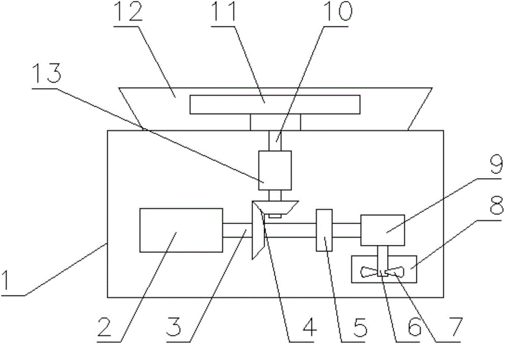
[0012] Such as figure 1 As shown, one embodiment of the present invention is: a drawing machine, including: machine base 1, motor 2, main shaft 3, drawing shaft 10, bevel gear 4, governor 13, drawing turntable 11, gear Disc 12, speed reducer 9, clutch 5, stirring shaft 6, blade 7 and stirring box 8, baffle disk 12 is arranged on the upper end of machine base 1, and baffle disk 12 is trumpet-shaped. The drawing turntable 11 is located in the stopper 12, the motor 2 is fixed inside the machine base 1, the main shaft 3 is connected with the motor 2, the main shaft 3 is set horizontally, and the bottom end of the drawing shaft 10 is connected with the main shaft 3 through a pair of bevel gears 4 , the drawing shaft 10 is perpendicular to the main shaft 3 , the top of the drawing shaft 10 passes through the base 1 , and the top of the drawing shaft 10 is connected with the drawing turntable 11 . The drawing shaft 10 is provided with a governor 13, the top of the stirring shaft 8 i...


PUM


Abstract

The invention discloses a throwing machine. The throwing machine comprises a base, a motor, a spindle, a throwing shaft, bevel gears, a speed regulator, a throwing rotary plate, a retaining plate, a speed reducer, a clutch, a stirring shaft, blades and a stirring tank. The throwing rotary plate is positioned in the retaining plate which is arranged at the upper end of the base, the spindle is connected with the motor which is fixed in the base, the bottom end of the throwing shaft is connected with the spindle through the pair of bevel gears, the top end of the throwing shaft is connected with the throwing rotary plate, and the throwing shaft is provided with the speed regulator. The top end of the stirring shaft is connected with the spindle through the speed reducer, the clutch is arranged between the spindle and the speed reducer, and the blades are mounted at the bottom end of the stirring shaft and positioned in the stirring tank. The throwing rotary plate and the stirring shaft are driven to rotate simultaneously by one motor, stirring and throwing can be carried out at the same time, and the throwing machine is especially suitable for beginners.

Description

technical field [0001] The invention relates to a ceramic manufacturing equipment, in particular to a drawing machine. Background technique [0002] The blanking machine is generally used to make ceramic blanks. The blanking machine is mainly composed of a machine base, a blanking turntable, a motor, and a governor. During the drawing process, the refined mud is manually placed on the drawing turntable, and the mud is drawn into a blank with both hands by the force of rotation. With the development of the ceramic industry, more and more people are learning ceramic manufacturing. For beginners, there are still many problems in the products obtained after learning the blank drawing, and repeated practice is required. Therefore, the products obtained after the practice are often remixed into mud, and at the same time carry out manual mud training, the existing billet drawing machine can only realize the billet drawing function, the function is single, and cannot well meet the ...

Claims


Application Information

Patent Timeline
Patent Type & Authority Applications(China)
IPC IPC(8): B28B1/02B28B17/00
CPCB28B1/02B28C1/16
Inventor 陈向阳
Owner ZHONGLI CERAMICS
Why Eureka
Try Eureka