Eureka AIR delivers breakthrough ideas for toughest innovation challenges, trusted by R&D personnel around the world.

Swing laser filler wire welding method for large-gap butt joint of aluminum alloy sheets

A technology of laser wire filling and aluminum alloy welding wire, applied in laser welding equipment, welding/welding/cutting items, welding equipment, etc., can solve the problems of limited welding size and joint form, low welding efficiency, etc., and reduce the dilution rate , high welding speed, and improved energy utilization

Active Publication Date: 2021-01-19
北京金炬科技有限公司
View PDF6 Cites 4 Cited by
  • Summary
  • Abstract
  • Description
  • Claims
  • Application Information

AI Technical Summary

Problems solved by technology

At the same time, the problems of low welding efficiency and limited welding size and joint form in solid phase welding also make it difficult to be widely used in flexible and complex aerospace structural parts.

Method used


Image

  • Swing laser filler wire welding method for large-gap butt joint of aluminum alloy sheets
  • Swing laser filler wire welding method for large-gap butt joint of aluminum alloy sheets
  • Swing laser filler wire welding method for large-gap butt joint of aluminum alloy sheets

Examples


Embodiment 1

[0047] Select 1.6mm thick SiC with 17% volume fraction p / 2009Al composite material is used as the test plate to be welded, and the welding is carried out according to the above-mentioned swing laser wire-filled welding method of large-gap butt joint of aluminum alloy thin plates. The welding parameters are as follows: the welding wire is 5356 aluminum alloy welding wire; Amplitude 1.0mm; swing frequency 200Hz; gap 1.0mm; laser power 3200W; welding speed 4.8m / min; wire feeding speed 11.2m / min.

Embodiment 2

[0049] Select 1.6mm thick SiC with 17% volume fraction p / 2009Al composite material is used as the test plate to be welded, and the welding is carried out according to the above-mentioned swing laser wire-filled welding method of large-gap butt joint of aluminum alloy thin plates. The welding parameters are as follows: the welding wire is 5356 aluminum alloy welding wire; Amplitude 1.0mm; swing frequency 200Hz; gap 1.2mm; laser power 3200W; welding speed 4.8m / min; wire feeding speed 11.2m / min.

Embodiment 3

[0051] Select 1.6mm thick SiC with 17% volume fraction p / 2009Al composite material is used as the test plate to be welded, and the welding is carried out according to the above-mentioned swing laser wire-filled welding method of large-gap butt joint of aluminum alloy thin plates. The welding parameters are as follows: the welding wire is 2319 aluminum alloy welding wire; Amplitude 1.0mm; swing frequency 200Hz; gap 1.0mm; laser power 3500W; welding speed 4.8m / min; wire feeding speed 9.6m / min.


PUM

PropertyMeasurementUnit
thicknessaaaaaaaaaa
widthaaaaaaaaaa
tensile strengthaaaaaaaaaa

Abstract

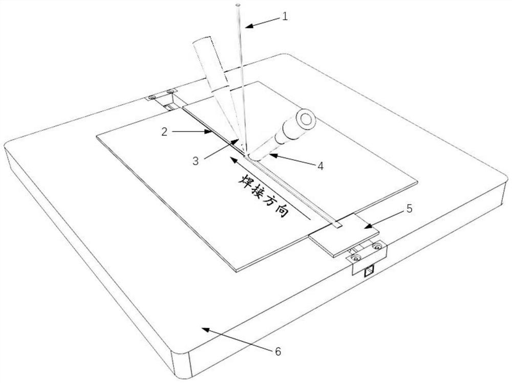
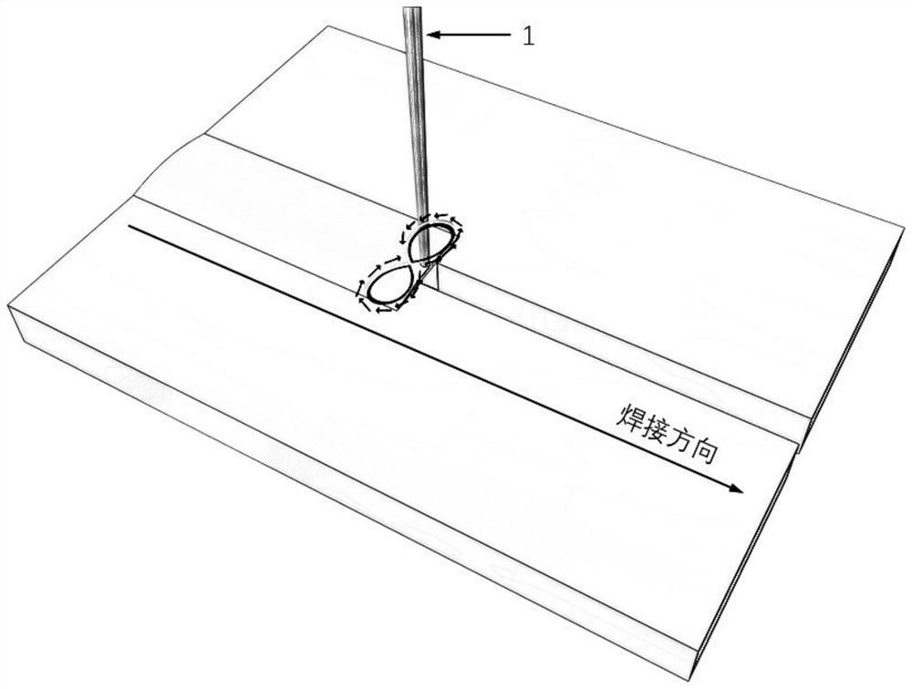
The invention discloses a swing laser filler wire welding method for large-gap butt joint of aluminum alloy sheets. The method comprises the following steps that the two aluminum alloy sheets are prepared, and a gap is reserved between butt joint surfaces of the two aluminum alloy sheets; a laser head, a wire feeding nozzle and a shielding gas nozzle are arranged above the gap; a first guide plateis pre-arranged at the welding starting end of the gap, and after a molten pool is formed on the first guide plate through laser beams, the molten pool is introduced into the welding starting end ofthe gap; and then the wire feeding nozzle and the laser head correspond to the gap and advance in the same direction, the whole gap is filled with aluminum alloy welding wires after the aluminum alloywelding wires are heated and melted through the laser beams, and welding work of the two aluminum alloy sheets is completed. Due to the fact that the gap is reserved, the melting amount of the laserbeams to the aluminum alloy sheets can be reduced as much as possible in the whole welding process, then the dilution rate of a welding joint can be reduced, generation of metallurgical reaction brittle phases can be reduced, meanwhile, the porosity of the joint can be reduced, and welding of conventional aluminum alloy, aluminum-based composite materials and additive manufacturing aluminum alloysheets can be achieved.

Description

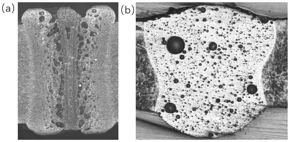
technical field [0001] The invention relates to the field of welding technology, in particular to a method for oscillating laser wire-filling welding of aluminum alloy thin plates with large gap butt joints. Background technique [0002] As a non-ferrous metal structural material, aluminum alloy is widely used for its low density, high specific strength, strong corrosion resistance, excellent electrical and thermal conductivity and other properties. With the development of modern science and technology such as aerospace, energy, ocean engineering, and transportation, people have put forward higher requirements for material performance, and various new aluminum alloy materials and new aluminum alloy manufacturing technologies have also emerged as the times require. Among them are new aluminum alloy materials represented by silicon carbide reinforced aluminum matrix composite materials, and new manufacturing technologies represented by 3D printing technology. For example: sil...

Claims


Application Information

Patent Timeline
Patent Type & Authority Applications(China)
IPC IPC(8): B23K26/211B23K26/70
CPCB23K26/211B23K26/702B23K2101/18B23K2103/10
Inventor 吴世凯齐恩语崔旭建张钧翀秦文斌
Owner 北京金炬科技有限公司
Why Eureka
Eureka Blog
Learn More