3d printer print head

A 3D printer and print head technology, applied in processing and manufacturing, liquid material additive processing, additive processing, etc., can solve problems such as difficult to achieve high-pressure rapid injection, difficult to achieve material diversity, and high production costs

Inactive Publication Date: 2017-09-01
SHENZHEN WANWEI IM TECH CO LTD
View PDF6 Cites 7 Cited by
  • Summary
  • Abstract
  • Description
  • Claims
  • Application Information

AI Technical Summary

Problems solved by technology

The consumables used in the existing FDM technology are filamentous materials, and ordinary industrial raw materials cannot be directly used, so the production cost is high
In addition, due to the limitation of filamentary materials, it is difficult to realize the diversity of m

Method used


Image

  • 3d printer print head
  • 3d printer print head
  • 3d printer print head

Examples


Embodiment Construction

[0016] The present invention will be described in further detail below in conjunction with the embodiments and with reference to the accompanying drawings.

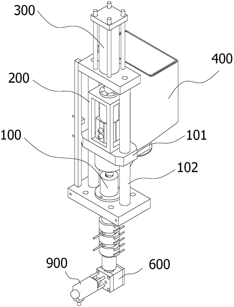
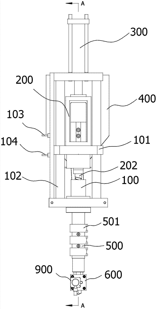
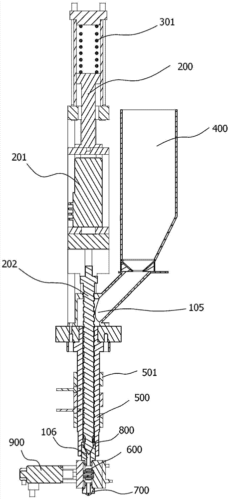
[0017] A print head for a 3D printer, please refer to Figure 1 to Figure 3 , including a housing 100, a feeding device 200 is arranged up and down in the housing 100, a pressure device 300 is arranged above the feeding device 200, and the outlet 106 of the feeding device 200 is communicated with by a volumetric metering pump 600 Nozzle 700, the feed device 200 includes a drive device 201 and a screw 202 driven to rotate by the drive device 201, a feed port 105 is arranged above the housing surrounding the screw rod 202, and a feed port 105 is arranged below the housing surrounding the screw rod 202 The end of the screw rod 202 is provided with a one-way valve 800 for the hot melt cavity 500 .

[0018] When the printing head is working, the granular, powdery or fluid raw material placed in the funnel 400 enters the casin...


PUM


Abstract

The invention discloses a printing head for a 3D printer. The printing head comprises a shell, wherein a feeding device is vertically slipped in the shell; a pressure device is arranged above the feeding device; an outlet of the feeding device is communicated with a nozzle through a volume metering pump; the feeding device comprises a driving device, and a screw rod driven by the driving device to rotate; a feeding port is formed surrounding the upper side of the shell of the screw rod; a hot melting cavity is formed surrounding the lower side of the shell of the screw rod; and a one-way valve is sleeved at the tail end of the screw rod. The printing head for the 3D printer has the advantages of use of multiple raw materials as printing materials, low cost and high printing preciseness.

Description

technical field [0001] The invention relates to a printing device, in particular to a printing head for a 3D printer which can use various raw materials as printing materials, has low cost and high printing precision. Background technique [0002] 3D printing technology is a rapid prototyping technology, which is based on digital model files, using metal, plastic, inorganic materials, etc., to construct objects by layer-by-layer printing. At present, the 3D printing technology that uses plastic as the consumable mostly adopts the fused deposition method (FDM technology), that is, after the filamentous hot-melt material is melted, it is extruded through a nozzle and deposited on a platform, and finally formed by layer-by-layer accumulation of materials. object. The consumables used in the existing FDM technology are filamentous materials, and ordinary industrial raw materials cannot be directly used, so the production cost is high. In addition, due to the limitation of fila...

Claims


Application Information

Patent Timeline
IPC IPC(8): B29C64/20B29C64/106B33Y30/00
Inventor 陈名乔
Owner SHENZHEN WANWEI IM TECH CO LTD
Why Eureka
Try Eureka