
No damage test device of permanent magnet magnetic field intensity

A technology of magnetic field strength and testing device, applied in the direction of the size/direction of the magnetic field, which can solve the problems such as the inability to guarantee the range of the tested magnetic field strength and the test accuracy, poor test result accuracy, limited volume and shape of the tested permanent magnet, etc. , to achieve the effect of convenient magnetic field strength, convenient operation and convenient movement

Active Publication Date: 2014-11-19
HARBIN XIANGKE NEW MATERIAL
View PDF5 Cites 3 Cited by
  • Summary
  • Abstract
  • Description
  • Claims
  • Application Information

AI Technical Summary

Problems solved by technology

[0005] The present invention proposes a permanent magnet in order to solve the problems that the test result accuracy of the existing permanent magnet magnetic field strength test equipment is poor, the volume shape of the measured permanent magnet is limited, and the range and test accuracy of the tested magnetic field strength cannot be guaranteed at the same time. Non-destructive testing device for magnetic field strength

Method used


Image

  • No damage test device of permanent magnet magnetic field intensity
  • No damage test device of permanent magnet magnetic field intensity
  • No damage test device of permanent magnet magnetic field intensity

Examples


specific Embodiment approach 1

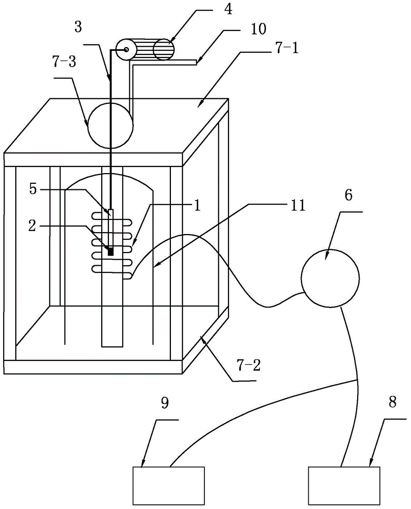
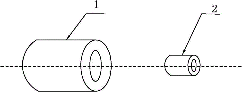
[0012] Specific implementation mode 1. Refer to figure 1 and figure 2 Specifically illustrate this embodiment, the non-destructive testing device of permanent magnet magnetic field strength described in this embodiment, permanent magnet 2 is measured object, and it comprises induction coil 1, telescopic mechanism 3, motor 4, permanent magnet carrier 5, signal detection Device 6 and temperature control box 11;

[0013] The induction coil 1 and the permanent magnet 2 are located in the temperature control box 11; the induction coil 1 is wound into an annular cylinder; the permanent magnet 2 is placed in the permanent magnet carrier 5, and one end of the telescopic mechanism 3 is connected to one end of the permanent magnet carrier 5, and the telescopic mechanism The other end of 3 is connected to the driving end of the motor 4; the permanent magnet 2 is located on the central axis of the induction coil 1; the signal output end of the induction coil 1 is the signal input end of...

specific Embodiment approach 2

[0017] Embodiment 2. This embodiment is a further description of the permanent magnet magnetic field strength non-destructive testing device described in Embodiment 1. In this embodiment, the signal detection device 6 is a sensitive ammeter or a sensitive voltmeter.

[0018] In this embodiment, the use of the sensitive ammeter and the sensitive voltmeter is used to measure the magnitude of the induced current of the induction coil 1, and the sensitive ammeter and the sensitive voltmeter themselves have relatively high precision, so the magnitude precision of the measured induced current is also relatively high , to further ensure the test accuracy of the device.

specific Embodiment approach 3

[0019] Embodiment 3. This embodiment is a further description of the non-destructive testing device for the magnetic field strength of the permanent magnet described in Embodiment 1. In this embodiment, it also includes a bracket 7 and a motor bracket 10;

[0020] The bracket 7 includes an upper baffle 7-1 and a lower baffle 7-2, the upper baffle 7-1 is fixedly connected with the lower baffle 7-2, and the upper baffle 7-1 has a circular hole 7-3;

[0021] The motor 3 is fixed on the motor bracket 10, and the motor bracket 10 is fixed on the upper surface of the upper partition 5-1; the induction coil 1 is fixed on the upper partition 7-1 and the lower partition 7-1. between 2;

[0022] The permanent magnet carrier 5 moves up and down through the circular hole 7-3.

[0023] The bracket and the motor bracket described in this embodiment are used to better complete the test work on the magnetic field strength of the permanent magnet. The use of the bracket ensures the position ...


PUM


Abstract

The invention relates to a no damage test device of permanent magnet magnetic field intensity, and relates to the field of the time stability test of the magnetic performance of a permanent magnet. The test device provided by the invention solves the problem that the existing permanent magnet magnetic field intensity test device has poor test result precision, is limited by the volume and the shape of a tested permanent magnet, and cannot ensure the test magnetic field intensity range and the test precision at the same time. The test device comprises an induction coil, the permanent magnet, a telescopic mechanism, a motor, a permanent magnet carrier, a signal detection device and a temperature control box. The induction coil and the permanent magnet are located in the temperature control box. The induction coil is wound into a circular cylinder. The permanent magnet is arranged in the permanent magnet carrier. One end of the telescopic mechanism is connected with one end of the permanent magnet carrier, and the other end of the telescopic mechanism is connected with the drive end of the motor. The permanent magnet is located on the center axis of the induction coil. The signal output end of the induction coil is connected with the signal input end of the signal detection device. The test device provided by the invention is suitable for testing the shape of the permanent magnet on the magnetic stability.

Description

technical field [0001] The invention relates to the field of time stability testing of permanent magnet magnetic properties. Background technique [0002] Permanent magnet materials have been widely used in computers, speakers, household appliances, instruments and meters, magnetic machinery, various motors, medical equipment and other equipment, especially when used in high-precision instruments and equipment, the reliability of permanent magnet materials is extremely high. important. The stability of permanent magnet materials can be divided into time stability, temperature stability, external magnetic field stability and chemical stability. Factors affecting the stability of permanent magnet materials can be classified into two categories. The first type is caused by the material itself. We call the degree of magnetic change of the material itself over time as time stability. Time stability is related to material composition, organizational structure, manufacturing pro...

Claims


Application Information

Patent Timeline
Patent Type & Authority Applications(China)
IPC IPC(8): G01R33/02
Inventor 武高辉耿洪斌丁伟姜龙涛苟华松陈国钦
Owner HARBIN XIANGKE NEW MATERIAL
Learn More