Supercharge Your Innovation With Domain-Expert AI Agents!

Transformer Capsule Oil Conservator

A technology of oil conservator and transformer, which is applied in the direction of transformer/inductor cooling, etc. It can solve the problems of hidden dangers in transformer operation, insufficient speed, many and miscellaneous pipelines, etc. It achieves convenient operation and maintenance, simple and reasonable structure, and reduces the cost of vacuum tubes Effect

Active Publication Date: 2017-08-08
南通晓星变压器有限公司
View PDF5 Cites 0 Cited by
  • Summary
  • Abstract
  • Description
  • Claims
  • Application Information

AI Technical Summary

Problems solved by technology

There are three types of vacuum oil filling in the current technology: the first is oil filling without an oil conservator, this oil filling method is to make the oil filling in the oil conservator under normal pressure, but it will cause some gas in the oil conservator and moisture will be integrated into the transformer, which will bring hidden dangers to the operation of the transformer; the second method is to fill oil with an oil conservator that is not resistant to vacuum. After the vacuum structure, the oil conservator is still filled with oil under normal pressure, which will also cause problems like the first oil filling method; the third method is to fill oil together with the vacuum-resistant oil conservator, which is the real way The full vacuum oiling can minimize the gas and water content in the oil, but the capsule of the capsule oil conservator is made of rubber, if the pressure difference between the inside and outside of the capsule is large when the oil conservator is in vacuum, the capsule will be damaged, causing The gas and impurities in the capsule enter the main body of the oil conservator, accelerating the aging of transformer oil
[0003] When the oil conservator is evacuated, the vacuuming pipes in the oil conservator are used, which takes a long time and is not fast enough; there are also pipes for the moisture absorber, oil injection pipes, and oil delivery pipes in the oil conservator, and the pipes are relatively Many and miscellaneous

Method used


Image

  • Transformer Capsule Oil Conservator

Examples


Embodiment Construction

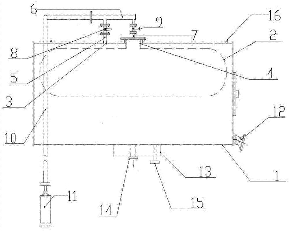
[0017] In order to enable those skilled in the art to better understand the solution of the present invention, the present invention will be further described in detail below in conjunction with the accompanying drawings and specific embodiments.

[0018] Such as figure 1 As shown, a transformer capsule oil conservator includes an oil conservator 1 and a capsule 2, the capsule 2 is set in the cavity of the oil conservator 1, and the oil conservator 1 is provided with a pipeline interface I3 and a pipeline interface II4, the pipeline interface I3 communicates with the cavity of the oil conservator 1, the pipeline interface II4 communicates with the capsule 2 and the pipeline interface II4 is connected to the capsule 2 in a sealed manner; the pipeline interface I3 connects with the joint pipe 6 through the pipeline I5 Connected and the connection is sealed, the pipeline interface II4 is connected to the joint pipe 6 through the pipeline II7 and the joint is sealed, the valve I8 ...


PUM


Abstract

The invention discloses a transformer capsule type oil conservator, which comprises an oil conservator and a capsule, and the capsule is arranged in the cavity of the oil conservator body, and is characterized in that the oil conservator is provided with a pipeline interface I and a pipeline Interface II, the pipeline interface I communicates with the cavity of the oil conservator, the pipeline interface II communicates with the capsule and the pipeline interface II and the capsule are sealed and connected; the pipeline interface I communicates with the union through the pipeline I and connects The joint of the pipeline II is connected to the joint pipe through the pipeline II and the joint is sealed, the valve I is set on the pipeline I, and the valve II is set on the pipeline II; the joint pipe is connected to the moisture absorber through a connecting pipe and the moisture absorber and The connecting pipes are detachably connected, and the inner diameter of the pipeline I is larger than that of the pipeline II. It can fully realize the integrated vacuuming of the transformer oil conservator and the capsule, and at the same time ensure that the pressure inside and outside the capsule is the same without causing damage; the vacuum tube is shared with the moisture absorber joint tube, which simplifies the structure, saves materials, and is convenient and quick for vacuum oiling.

Description

technical field [0001] The invention relates to the electric power industry, in particular to a transformer oil conservator, in particular to a transformer capsule oil conservator. Background technique [0002] In order to effectively reduce the air bubbles and moisture in the transformer body and oil, improve the insulation level of the transformer and the electrical performance of the oil, the vacuum oiling process is now used. There are three types of vacuum oil filling in the current technology: the first is oil filling without an oil conservator, this oil filling method is to make the oil filling in the oil conservator under normal pressure, but it will cause some gas in the oil conservator and moisture will be integrated into the transformer, which will bring hidden dangers to the operation of the transformer; the second method is to fill oil with an oil conservator that is not resistant to vacuum. After the vacuum structure, the oil conservator is still filled with o...

Claims


Application Information

Patent Timeline
Patent Type & Authority Patents(China)
IPC IPC(8): H01F27/14
Inventor 江世云范培宁于镇法王大勇
Owner 南通晓星变压器有限公司
Features
  • R&D
  • Intellectual Property
  • Life Sciences
  • Materials
  • Tech Scout
  • Unparalleled Data Quality
  • Higher Quality Content
  • 60% Fewer Hallucinations
Learn More