
Bathroom exhaust fan automatic and manual dual-purpose switch circuit

A switching circuit, exhaust fan technology, applied in electronic switches, electrical components, pulse technology and other directions, can solve the problems of unsafe use, waste of electric energy, shorten the service life of exhaust fans, etc., and achieve the effect of saving electric energy

Active Publication Date: 2017-05-03
南通扬宇电子有限公司
View PDF6 Cites 0 Cited by
  • Summary
  • Abstract
  • Description
  • Claims
  • Application Information

AI Technical Summary

Problems solved by technology

[0002] Most of the family bathrooms are also used as bathrooms. The exhaust fan in the bathroom is not only used for ventilation and deodorization, but also used to remove water vapor when people take a bath. The switch of the exhaust fan is generally operated manually. When people find that water vapor is permeating the air during bathing, manually opening the exhaust fan to take a breath when the whole body is soaked will cause unsafe problems and inconvenient use. Waste and shorten the service life of the exhaust fan

Method used


Image

  • Bathroom exhaust fan automatic and manual dual-purpose switch circuit

Examples


Embodiment Construction

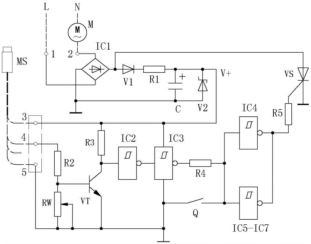
[0012] Example attached figure 1 In the illustrated embodiment, an automatic and manual two-purpose switch circuit for a toilet exhaust fan consists of a power interface a (1), a power interface b (2), a rectifier integrated block (IC1), an isolation diode (V1), and a step-down Resistor (R1), filter capacitor (C), Zener diode (V2), signal interface (4), bias resistance a (R2), variable resistance (RW), transistor (VT), bias resistance b (R3) ), NOT gate a (IC2), NOT gate b (IC3), isolation resistance (R4), manual switch (Q), NOT gate c (IC4), drive resistance (R5) and unidirectional thyristor (VS) , Where: the two input ends of the rectifier integrated block (IC1) are connected to the power interface a (1) and the power interface b (2) respectively, and the anode of the rectifier integrated block (IC1) is connected to the anode and the single terminal of the isolation diode (V1). To the anode of the thyristor (VS), the cathode of the isolation diode (V1) is connected to the fi...


PUM


Abstract

The invention relates to an automatic and manual dual-purpose switching circuit for the exhaust fan of a restroom and relates to a controlling circuit for the exhaust fan. The automatic and manual dual-purpose switching circuit comprises a power interface, a signal interface, a biasing resistance a, a variable resistance, a triode, a biasing resistance b, NOT gates, an isolation resistance, a manual switch, a driving resistance, a one-way thyristor, wherein the first foot of the biasing resistance a is connected to the signal interface; the second foot of the biasing resistance a is connected to the first foot of the variable resistance and the base of the triode; the collecting electrode of the triode is connected to the input end of a NOT gate a and the second foot of the biasing resistance b; the first foot of the biasing resistance b is connected to a working power source; the output end of the NOT gate a is connected to the input end of a NOT gate b; the output end of the NOT gate b is connected to the input end of a NOT gate c and the second end of the manual switch through the isolation resistance; the output end of the NOT gate c is connected to the controlling electrode of the one-way thyristor. According to the invention, the exhaust fan can be automatically turned on for the exclusion of water vapor based on the humidity of the restroom, potential safety hazards can be eliminated, and the automatic and manual dual-purpose switching circuit can bring convenience to people.

Description

Technical field [0001] The invention relates to an electronic circuit, in particular to an exhaust fan control circuit. Background technique [0002] Most of the family bathrooms are also used as baths. The exhaust fans in the bathrooms are used to ventilate and remove odors. They are also used to remove water vapor when people take a bath. The switches of the exhaust fans are generally operated manually. When people find that water vapor is permeated during the bathing process, manually turning on the exhaust fan for ventilation when the whole body is soaked will cause unsafe problems and inconvenient use. For example, turning on the exhaust fan before taking a bath will cause electricity Waste and shorten the service life of the exhaust fan. Summary of the invention [0003] The purpose of the present invention is to provide an automatic and manual switch circuit for the toilet exhaust fan. When the odor is removed at ordinary times, the exhaust fan is manually opened for venti...

Claims


Application Information

Patent Timeline
Patent Type & Authority Patents(China)
IPC IPC(8): H03K17/94H03K17/96
Inventor 蒋小芳
Owner 南通扬宇电子有限公司
Learn More