LTE system uplink power control method and system

A control method and power technology, applied in power management, wireless communication, electrical components, etc., can solve the problems of macro base station uplink power transmission interference, excessive uplink power, etc.

Active Publication Date: 2014-11-19
FUJIAN SUNNADA TECH CO LTD
View PDF5 Cites 2 Cited by
  • Summary
  • Abstract
  • Description
  • Claims
  • Application Information

AI Technical Summary

Problems solved by technology

[0003] The technical problem to be solved by the present invention is to provide a method and system for controlling the uplink power of an LTE syst

Method used


Image

  • LTE system uplink power control method and system
  • LTE system uplink power control method and system
  • LTE system uplink power control method and system

Examples


Embodiment 1

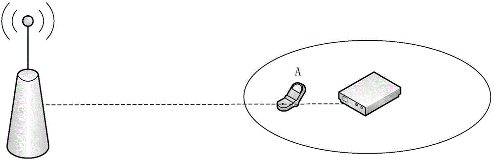
[0085] Please refer to image 3 , Embodiment 1 of the present invention is:

[0086] Taking mobile phone A as an example, when the coverage relationship between the macro base station and the nanocell base station, and the location of mobile phone A residing on the macro base station are as follows: image 3 As shown, the technical solution of the present invention can be used to adjust the uplink transmission power of the mobile phone. The specific process is as follows:

[0087] 1. Mobile phone A residing in the macro base station has uplink interference to the Nanocell;

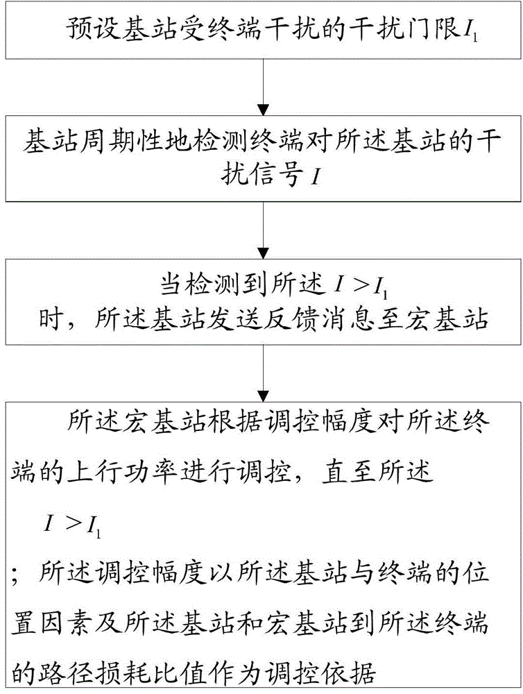
[0088] 2. An interference threshold I is preset on the Nanocell 1 , and the Nanocell periodically checks the uplink interference I of the mobile phone A to it;

[0089] 3. When Nanocell finds that I>I 1 , it means that mobile phone A interferes too much with Nanocell, and Nanocell needs to notify mobile phone A to adjust the uplink transmission power to reduce the interference to itself;

[0090] 4. ...

Embodiment 2

[0094] Please refer to Figure 4 , the second embodiment of the present invention is:

[0095] The Nanocell base station presets an interference threshold I 1 , Nanocell periodically detects MUE interference I, when Nanocell detects I>I 1 , send a bit of information "1" to the macro base station covering it through the S1 port. After the macro base station receives "1", it sends "1" to the MUE user terminal. If the macro base station does not receive "1", it sends "0" to the MUE user terminal. If the user terminal MUE receives the indication "0", it will also transmit according to the real-time uplink transmission power; if it receives the indication "1", it will continuously reduce the uplink power until it receives the indication "0".

[0096] After receiving the interference indication signal, the power adjustment formula is as follows:

[0097] P t =P t-1 +Δ T , where P t is the power of this cycle, P t-1 is the magnitude of the power in the previous cycle, Δ T i...


PUM


Abstract

The invention provides an LTE system uplink power control method and a system. The method comprises steps: the threshold I1 of interference from a terminal on a base station is preset; the base station periodically detects interference signals I from the terminal on the base station; when I is detected to be greater than I1, the base station sends a feedback message to a macro base station; the macro base station regulates the uplink power of the terminal according to the regulation range deltaT until I is smaller than I1; and the regulation range deltaT uses position factors of the base station and the terminal and the path loss ratio of the base station and the macro base station to the terminal to serve as the regulation basis. When the base station detects that the interference signals of the terminal on the base station exceed the interference threshold, the regulation range obtained when the macro base station uses the position factors of the base station and the terminal and the path loss ratio of the base station and the macro base station to the terminal to serve as the regulation basis regulates the uplink power of the terminal until the interference signals are reduced to the preset interference threshold, and the problem that overlarge terminal uplink power causes interference to uplink power transmission of the micro base station can be solved.

Description

technical field [0001] The present invention relates to the technical field of wireless communication, in particular to a method and system for controlling uplink power of an LTE system. Background technique [0002] In the existing LTE system, Nanocell is a miniaturized, low-power base station, which is mainly deployed in indoor environments such as offices or homes, and has the advantages of low cost, convenient access, and increased capacity of macrocellular networks. The deployment process of Nanocell is simple and can be self-configured by users. Therefore, the topology of the network will change in real time. With the widespread use of Nanocell, its impact on the performance of macrocellular networks will become more and more concerned. The most common and important usage scenario in the topology relationship between Nanocell and macro cellular network is that the coverage of Nanocell is completely within the coverage of the macro base station. In this scenario, if the...

Claims


Application Information

Patent Timeline
IPC IPC(8): H04W52/14
Inventor 何劲财王磊
Owner FUJIAN SUNNADA TECH CO LTD
Why Eureka
Try Eureka