Walking power generation shoes for generating power through flowing liquid

A technology of flowing liquid and generating shoes, applied in the field of shoes, can solve the problems of frequent charging and the gap of battery life of mobile phones.

Inactive Publication Date: 2014-11-26
郑振妍
View PDF4 Cites 6 Cited by
  • Summary
  • Abstract
  • Description
  • Claims
  • Application Information

AI Technical Summary

Problems solved by technology

[0002] In today's society, people are increasingly dependent on small electronic products such as mobile phones and tablet computers. However, there is a big gap between the battery life of mobile phones and people's actual needs, and frequent charging is often required

Method used


Image

  • Walking power generation shoes for generating power through flowing liquid
  • Walking power generation shoes for generating power through flowing liquid

Examples


Embodiment 1

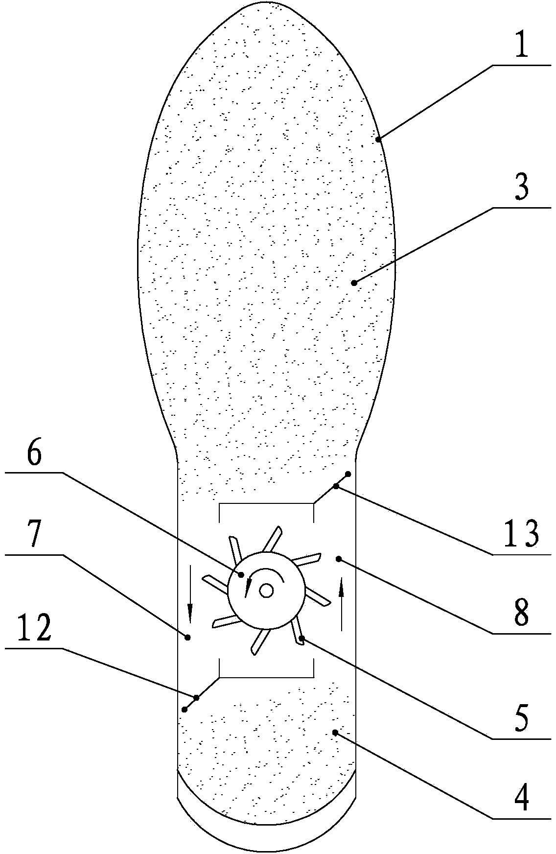
[0019] refer to figure 1 , a walking power generation shoe using flowing liquid to generate electricity, comprising a sole 1 and an upper 2, a first liquid bag 3 is arranged on the sole 1 corresponding to the position of the forefoot, and a second liquid bag is arranged on the sole 1 corresponding to the position of the heel 4. The first liquid bag 3 and the second liquid bag 4 are filled with liquid, preferably, the filling liquid is daily water. An impeller 5 is arranged between the first liquid bag 3 and the second liquid bag 4, and the blades of the impeller 5 are arranged obliquely. The one-way passage of bag 4, the blade of impeller 5 stretches in the one-way passage. The one-way channel includes a first channel 7 and a second channel 8. The first channel 7 is provided with a first valve 12 that opens toward the second liquid bag 4; The liquid in the first liquid bag 3 flows to the second liquid bag 4 through the first channel 7 , and the liquid in the second liquid ba...

Embodiment 2

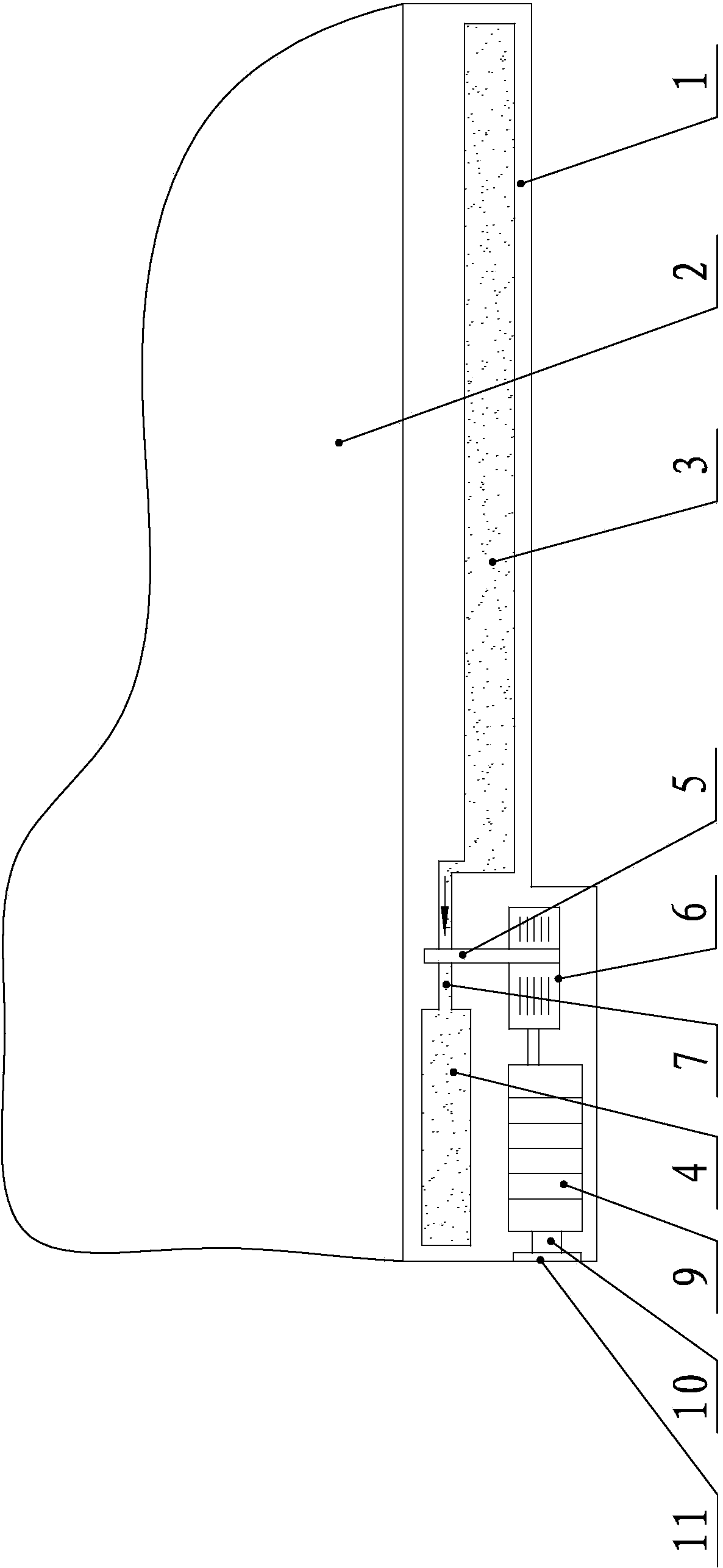
[0021] refer to figure 2 , another walking power generation shoe with a built-in battery 9 provided by this embodiment, its structure is basically the same as that of the first embodiment, including a sole 1 and a vamp 2, and a first A liquid bag 3, a second liquid bag 4 is arranged on the shoe sole 1 corresponding to the position of the heel, and the first liquid bag 3 and the second liquid bag 4 are filled with liquid. An impeller 5 is arranged between the first liquid bag 3 and the second liquid bag 4, and the impeller 5 is connected to a micro-generator 6. A first channel 7 and a second channel 8 are respectively arranged on both sides of the impeller 5, and the liquid in the first liquid bag 3 passes through The first channel 7 flows to the second liquid bag 4 , and the liquid in the second liquid bag 4 flows to the first liquid bag 3 through the second channel 8 . When the liquid flows through the first channel 7 and the second channel 8, the impeller 5 is driven to ro...


PUM


Abstract

The invention discloses a pair of walking power generation shoes for generating power through flowing liquid. Each shoe comprises a shoe sole and a vamp. A first liquid bag is arranged on the portion, corresponding to one foot sole, in each shoe sole, a second liquid bag is arranged on the portion, corresponding to one heel, in each shoe sole, and each first liquid bag and each second liquid bag are filled with liquid; impellers are arranged between each first liquid bag and the corresponding second liquid bag and connected with a micro-generator, and the two sides of the impellers are provided with one-way passageways respectively for connecting the corresponding first liquid bag with the corresponding second liquid bag. Liquid flows through the one-way passageways to drive the corresponding impellers to rotate to drive the corresponding micro-generator to generate power. The shoes generate power through energy under the feet generated when people walk, and small electronic products can be charged at any time and in any place, so that long runtime of the electronic products such as mobile phones can be kept when people go out; meanwhile, due to the fact that the liquid bags at the bottoms of the shoes are filled with water or other liquid, the specific heat ratio is larger than that of air, the air temperature change lags, and therefore the shoes have the functions of being warm in winter and cool in summer.

Description

technical field [0001] The invention relates to a shoe, in particular to a walking power generation shoe which utilizes flowing liquid to generate power. Background technique [0002] In today's society, people are increasingly dependent on small electronic products such as mobile phones and tablet computers. However, there is a big gap between the battery life of mobile phones and people's actual needs, and frequent charging is often required. When people go out and cannot charge their mobile phones, but need to keep the battery life of their mobile phones for a long time, they need a device that can charge their mobile phones anytime and anywhere. [0003] When a person walks, as the footsteps rise and fall, there will be a certain amount of energy loss on the shoes. If this energy can be stored in the form of electric energy, small electronic products such as mobile phones can be charged anytime and anywhere. Long battery life is achieved. Contents of the invention ...

Claims


Application Information

Patent Timeline
Patent Type & Authority Applications(China)
IPC IPC(8): A43B3/00F03B13/00
Inventor 陈振圳
Owner 郑振妍
Why Eureka
Try Eureka