
A distance-measuring system and a distance-measuring method for optical flow catadioptric cameras with coaxial central distance

A technology of distance measurement system and distance measurement method, applied in the field of computer vision, to achieve the effect of easy analysis and processing

Inactive Publication Date: 2016-03-30
ZHEJIANG UNIV
View PDF1 Cites 0 Cited by
  • Summary
  • Abstract
  • Description
  • Claims
  • Application Information

AI Technical Summary

Problems solved by technology

[0004] Combining the characteristics of optical flow and catadioptric cameras, aiming at the shortcomings of existing catadioptric cameras, the purpose of the present invention is to provide a distance measuring system and a distance measuring method for optical flow catadioptric cameras with equal coaxial center distances

Method used


Image

  • A distance-measuring system and a distance-measuring method for optical flow catadioptric cameras with coaxial central distance
  • A distance-measuring system and a distance-measuring method for optical flow catadioptric cameras with coaxial central distance
  • A distance-measuring system and a distance-measuring method for optical flow catadioptric cameras with coaxial central distance

Examples


Embodiment Construction

[0029] The present invention will be more fully described below in conjunction with the accompanying drawings.

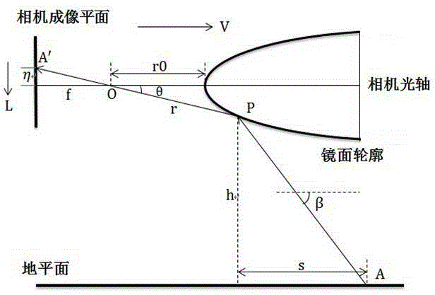
[0030] like figure 1 As shown, the system of the present invention includes a rotator mirror and a perspective camera coaxially placed opposite each other, the central symmetry axis of the rotator mirror and the optical axis of the perspective camera are collinear, and the distance between the vertex of the rotator mirror and the optical center of the perspective camera is Fixed, the measured object is placed under the mirror of the rotating body, and the measured object is regarded as a space point. The incident light of the space point of the measured object is reflected by the mirror and imaged to the perspective camera, and the imaging image is collected by the perspective camera. The rotating body mirror has Specular profile with equal optical flow properties. The system of the invention can be installed on aircrafts such as unmanned aerial vehicles to perform...


PUM


Abstract

The invention discloses a same-axis-center-distance equal-optical-flow catadioptric camera distance measurement system and a distance measurement method thereof. A center symmetry axis of a rotating body mirror plane and the optical axis of a perspective camera are collinear and have a fixed distance; a measured object is placed below the rotating body mirror plane, incident light of a measured object space point is reflected through the mirror plane and then imaged to the perspective camera, and the rotating body mirror plane has a mirror plane contour with an equal-optical-flow characteristic. The method comprises the steps: firstly building a simulation environment, and setting system parameters to obtained a relational expression between the axis center distance and the optical flow value; then actually measuring the distance, and after the camera acquires an image, calculating the optical flow value of the measured object space point at an imaged position on a camera imaging plane; and calculating the axis center distance from the measured object space point to the camera optical axis by using the relational expression, and thus achieving the distance measurement. With utilization of the equal-optical-flow characteristic of the rotating body mirror plane, the corresponding relationship is formed among the measured object space point, the camera optical axis and the optical flow, and thus the distance of a scene can be directly measured; and the system and the method can be used for unmanned aerial vehicle navigation and collision avoidance, and detect the height to the ground and the distance to obstacles.

Description

technical field [0001] The invention relates to a ranging system and a ranging method in the field of computer vision. Specifically, it relates to a distance measuring system and a distance measuring method for a coaxial central distance equal optical flow catadioptric camera. Background technique [0002] Compared with other sensors (ultrasonic distance sensor, lidar, etc.), the image sensor has a large amount of information, is cheap, and has mature technology. However, due to the large amount of information carried by the image sensor and the ambiguity of the information, it is extremely difficult to extract effective information in the image. Optical flow is the change of the object in the image, so it contains a lot of information about the motion of the object. A large amount of evidence, such as literature 1 (Srinivasan, MandyamV., and Shaowu Zhang. "Visual motorcomputationsininsects."Annu.Rev.Neurosci.27(2004):679-696.), shows that many insects control the speed of...

Claims


Application Information

Patent Timeline
Patent Type & Authority Patents(China)
IPC IPC(8): G01C3/30
CPCG01C3/30
Inventor 项志宇马子昂
Owner ZHEJIANG UNIV
Learn More