Optical film, manufacturing method thereof, backlight module and display device

A technology for optical film layers and manufacturing methods, which is applied in lamination devices, chemical instruments and methods, optics, etc., can solve problems such as increased production costs, and achieve the effects of saving material costs and reducing production costs

Inactive Publication Date: 2014-11-26
HEFEI BOE DISPLAY LIGHT +1
View PDF4 Cites 11 Cited by
  • Summary
  • Abstract
  • Description
  • Claims
  • Application Information

AI Technical Summary

Problems solved by technology

[0004] In order to solve the above problems, the present invention provides an optical film layer and its manufacturing method, a backlight module and a display device, which are used to solve the problem in the prior art that the production cost is greatly increased due to the frequent replacement of the glue

Method used


Image

  • Optical film, manufacturing method thereof, backlight module and display device
  • Optical film, manufacturing method thereof, backlight module and display device
  • Optical film, manufacturing method thereof, backlight module and display device

Examples


Embodiment 1

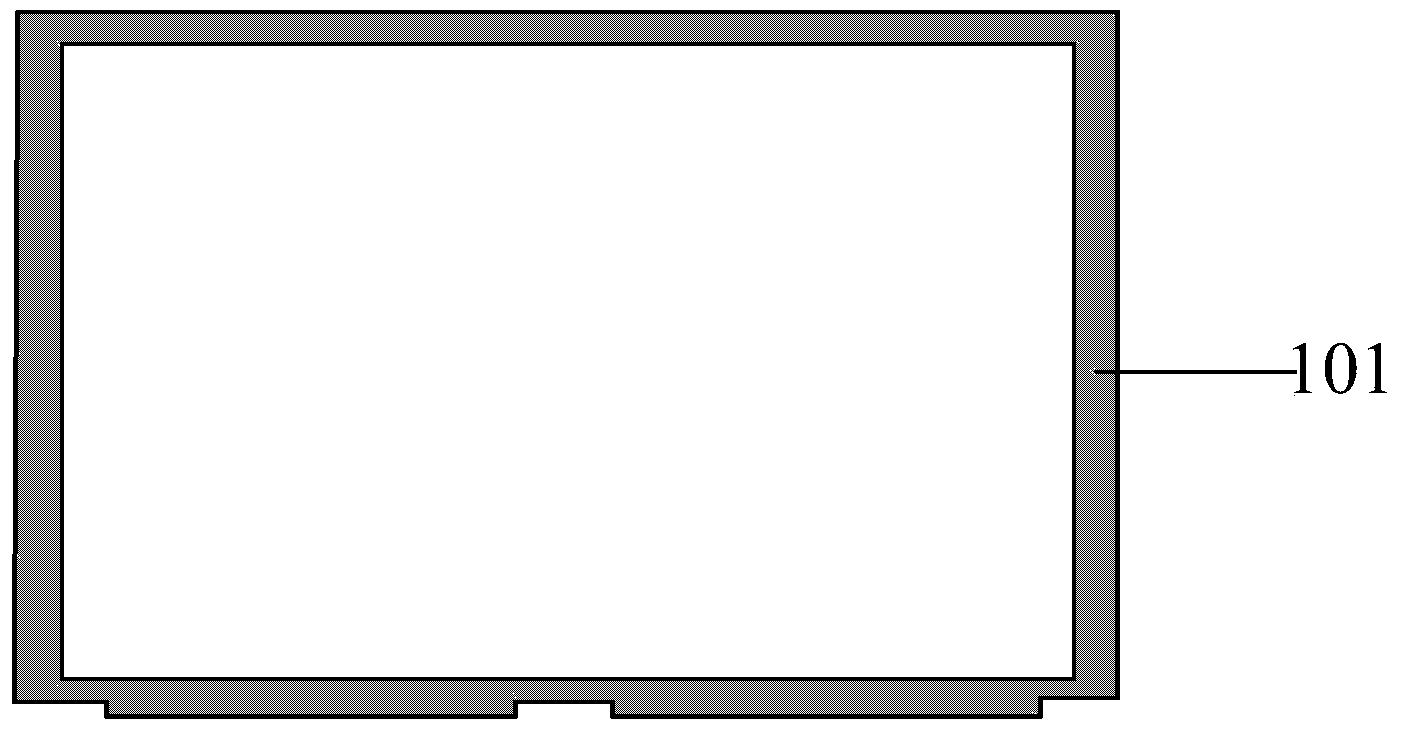
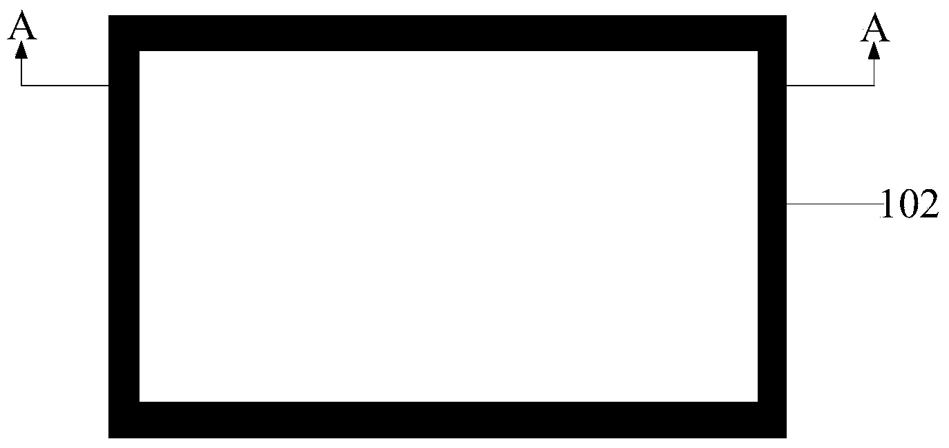
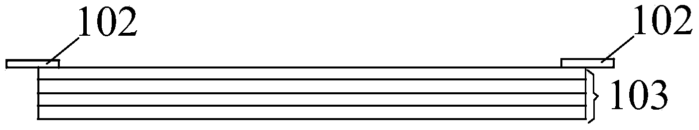
[0052] figure 2 It is a schematic structural diagram of an optical film layer provided in Embodiment 1 of the present invention, image 3 for figure 2 A-A cross-section of the optical layer shown. Such as figure 2 , image 3 As shown, the optical film layer includes a light-shielding structure 102 and an optical film group 103, the light-shielding structure 102 is arranged on the edge of the optical film group 103, and the light-shielding structure 103 is used to shield the optical film group light leaks at the edges. Preferably, the optical film set includes a prism sheet, a diffusion sheet, and a composite prism sheet. Optionally, the light shielding structure 102 is partially located on the edge of the optical film set 103 and partially located outside the optical film set 103 .

[0053] Figure 4 It is a schematic diagram of the application of the optical film layer in this embodiment. Such as Figure 4 As shown, the optical film set 103 is located on the light...

Embodiment 2

[0059] This embodiment provides a backlight module, including the optical film layer provided in Embodiment 1. For details, please refer to the description in Embodiment 1 above, which will not be repeated here.

[0060] In the backlight module provided by this embodiment, the light-shielding structure is arranged on the edge of the optical film group, which saves material cost, attachment cost and loss cost of related materials, thereby greatly reducing production cost.

Embodiment 3

[0062] This embodiment provides a display device, including a backplane, a plastic frame, a display panel, and the backlight module provided in Embodiment 2. see Figure 4 and Figure 5 , the display panel (not shown in the figure) is located on the light emitting side of the backlight module, the plastic frame 105 is located on the outside of the display panel and the backlight module, and the back plate 106 is wrapped in the The backlight module and the outside of the plastic frame 105 . For details about the optical film layer and the backlight module, reference may be made to the descriptions in Embodiment 1 and Embodiment 2 above, and will not be repeated here.

[0063] In the display device provided by this embodiment, the light-shielding structure is arranged on the edge of the optical film group, which saves material cost, attachment cost and loss cost of related materials, thereby greatly reducing production cost.


PUM


Abstract

The invention provides an optical film, a manufacturing method thereof, a backlight module and a display device. The optical film comprises a shading structure and an optical diaphragm group. The shading structure is arranged on the edge of the optical diaphragm group, and the shading structure is used for shading leaked light on the edge of the optical diaphragm group. According to the optical film, the manufacturing method of the optical film, the backlight module and the display device, the shading structure is arranged on the edge of the optical diaphragm group, the material cost, the attaching cost and the loss cost of related materials are saved, and therefore the production cost is greatly reduced.

Description

technical field [0001] The invention relates to the field of display technology, in particular to an optical film layer and a manufacturing method thereof, a backlight module and a display device. Background technique [0002] In the field of liquid crystal display, the backlight module, especially the backlight module of small and medium-sized products, places the optical film set on the top of the product, so that there are problems such as light leakage and bright lines on the display screen around the edges of the backlight module. Aiming at the above problems, the solution provided by the prior art is to use a word-of-mouth glue on the edge of the optical film set. figure 1 It is a schematic structural diagram of an optical film layer in the prior art. Such as figure 1 As shown, the word-of-mouth glue 101 is in the shape of word-of-mouth around the circle. [0003] However, the above-mentioned solution has the following disadvantages: the said glue is thin and narrow...

Claims


Application Information

Patent Timeline
Patent Type & Authority Applications(China)
IPC IPC(8): G02F1/13357G02F1/1335B32B37/00
Inventor 李德君薛银艳韦飞胡善芝
Owner HEFEI BOE DISPLAY LIGHT
Why Eureka
Try Eureka