Inner driving type passive clamping piezoelectric actuator
A piezoelectric driver and internal drive technology, applied in the direction of piezoelectric effect/electrostrictive or magnetostrictive motors, electrical components, generators/motors, etc., can solve the problem of slow motion of the driver and high machining accuracy requirements , Power failure cannot self-lock and other problems, to achieve the effect of overcoming power failure cannot self-lock, stable and reliable output displacement, and lower processing accuracy requirements
- Summary
- Abstract
- Description
- Claims
- Application Information
AI Technical Summary
Problems solved by technology
Method used
Image
Examples
specific Embodiment approach 1
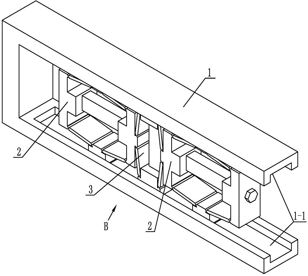
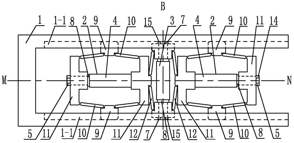
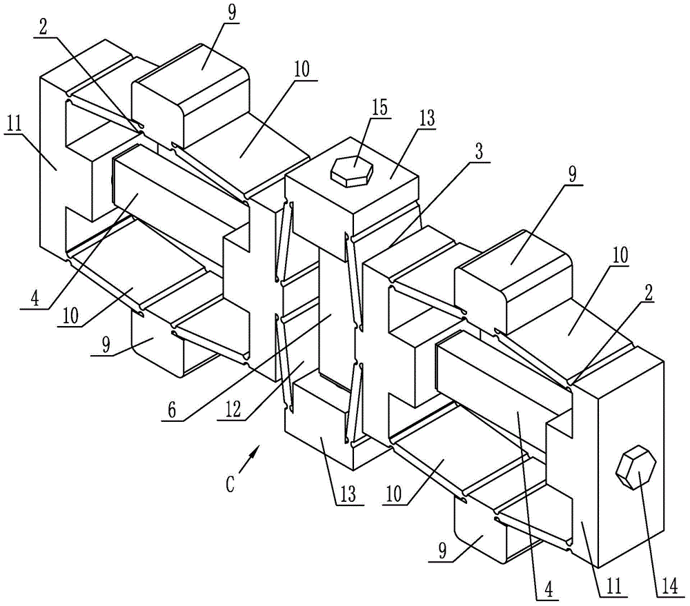
[0011] Specific implementation mode one: combine Figure 1-Figure 5 Illustrate that an internally driven passive clamping piezoelectric driver of this embodiment includes a guide rail 1, a driving body 3, a driving piezoelectric stack 6, two clamping piezoelectric stacks 4 and two clamping bodies 2; the guide rail 1 is a П-shaped guide rail, and the two arms of the guide rail 1 are set horizontally;
[0012] Each clamping body 2 includes a clamping piezoelectric stack pretensioner 5, two flexible hinges 10 for clamping triangular amplification, two clamping piezoelectric stack supports 11 and two clamping heads 9; The clamping triangle enlarged flexible hinge 10 is arranged symmetrically with the center line MN of the guide rail 1, and the middle parts of the two clamping triangle enlarged flexible hinges 10 are each equipped with a clamping head 9, and the two clamping triangle enlarged flexible hinges 10 A clamp piezoelectric stack support body 11 is installed at both ends,...
specific Embodiment approach 2
[0015] Specific implementation mode two: combination figure 2 Note that each flexible hinge 10 with enlarged clamping triangle in this embodiment is a straight circular flexible hinge with enlarged triangle clamping, and a clamping head 9 is connected to the outside of the central circular segment of each flexible hinge 10 with enlarged clamping triangle. Such arrangement has a compact structure, can be used in different occasions, can achieve precise resolution, high motion accuracy, and has good dynamic characteristics, which can greatly reduce the processing accuracy requirements of guide rails and clamping bodies. Others are the same as in the first embodiment.
specific Embodiment approach 3
[0016] Specific implementation mode three: combination figure 2 Note that each flexible hinge 12 driven by triangular enlargement in this embodiment is a straight circular flexible hinge driven by triangular enlargement. The stack supports 11 are connected. Such setting improves the walking speed of the driver, achieves precise resolution and high motion precision. Others are the same as in the first or second embodiment.
PUM
 Abstract
Description
Claims
Application Information
 - R&D
- Intellectual Property
- Life Sciences
- Materials
- Tech Scout
- Unparalleled Data Quality
- Higher Quality Content
- 60% Fewer Hallucinations
Browse by: Latest US Patents, China's latest patents, Technical Efficacy Thesaurus, Application Domain, Technology Topic, Popular Technical Reports.
© 2025 PatSnap. All rights reserved.Legal|Privacy policy|Modern Slavery Act Transparency Statement|Sitemap|About US| Contact US: help@patsnap.com


