Positioning and clamping device for cylindrical parts

A technology for positioning and clamping and parts, applied in auxiliary devices, auxiliary welding equipment, welding/cutting auxiliary equipment, etc., can solve the problems of time-consuming, labor-intensive, low-efficiency, and poor clamping accuracy, and achieves increased flexibility and low production costs. , the effect of simple and reasonable structure

Inactive Publication Date: 2021-03-05
SICHUAN AEROSPACE LONG MARCH EQUIP MFG CO LTD
View PDF8 Cites 7 Cited by
  • Summary
  • Abstract
  • Description
  • Claims
  • Application Information

AI Technical Summary

Problems solved by technology

This clamping method is not only time-consuming and laborious, but also has low efficiency and poor clamping accuracy.

Method used


Image

  • Positioning and clamping device for cylindrical parts
  • Positioning and clamping device for cylindrical parts
  • Positioning and clamping device for cylindrical parts

Examples


Embodiment 1

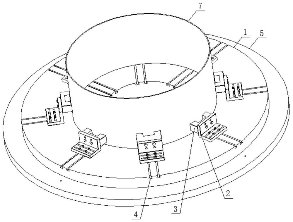
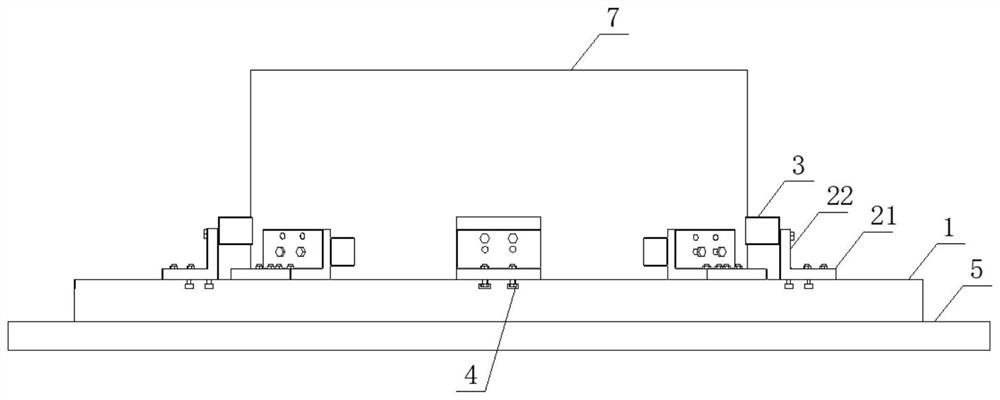
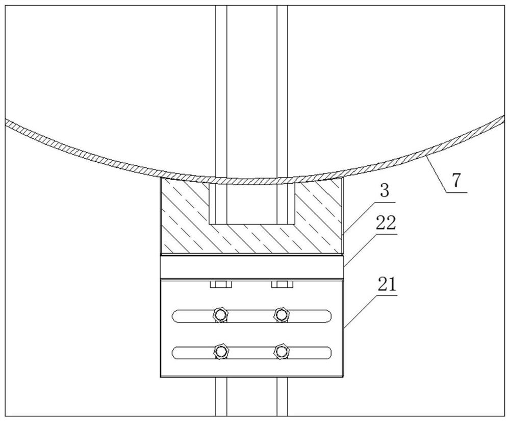
[0026] like Figures 1 to 3 As shown, this embodiment provides a positioning and clamping device for cylindrical parts 7, including a base 5, a tray 1, a positioning bent plate 2, and a top block 3; wherein, the tray 1 is an annular disk fixed on the upper part of the base 5; the tray 1. A number of slideways 4 are uniformly distributed in the circumferential direction. The cross section of the slideway 4 is inverted T-shaped and extends from the outer circle of the tray 1 to the inner circle of the tray 1. Two adjacent slideways 4 are arranged in parallel to form a slideway group. The slideway group is evenly distributed on the upper part of the tray 1 in the circumferential direction; the positioning bent plate 2 includes a positioning plate 21 and a mounting plate 22, and the positioning plate 21 is provided with waist-shaped mounting holes that are adapted to the positions of the two slideways 4 of a set of slideway groups. The length of the shaped mounting hole is adapted...

Embodiment 2

[0033] like Figure 4As shown, this embodiment is based on the positioning and clamping device of Embodiment 1, and a buffer pad 6 is provided at the end of the top block 3 away from the mounting plate 22. One end of the cushion pad 6 is detachably connected to the top block 3, and the other end is provided with the to-be-installed The arc surface of the outer wall of the clamping part 7 is adapted. After clamping, the top block 3 squeezes the buffer pad 6 to clamp the cylindrical part 7. During use, replace the suitable buffer pad 6 for pipes of different diameters , in this embodiment, a dovetail groove is provided at the end where the top block 3 is connected to the cushion pad 6, and a connecting block adapted to the dovetail groove is arranged on the cushion pad 6, and the cushion pad 6 is embedded in the dovetail groove through the connecting block. Various buffer pads 6 are mounted on the connection blocks. Cushion pad 6 is rubber material, when can avoid clamping forc...


PUM


Abstract

The invention provides a positioning and clamping device for cylindrical parts. The positioning and clamping device comprises a tray, a positioning bent plate and a top block, wherein a plurality of slideways are uniformly distributed on the tray in the circumferential direction, and the slideways have inverted T-shaped cross sections and extend from the edge of the tray to the middle of the tray.The positioning bent plate comprises a positioning plate and a mounting plate, wherein the positioning plate is fixed on the slideways of the tray through bolts, and the mounting plate is verticallyfixed on the upper portion of the positioning plate. The top block is arranged on the side, close to the middle of the tray, of the mounting plate. According to the positioning and clamping device forthe cylindrical parts, the positioning bent plate is installed on the slideways through the bolts, the positioning bent plate can slide along the slideways by unscrewing the bolts so that the parts can be clamped and loosened, and the positioning and clamping device is simple and reasonable in structure, low in manufacturing cost, suitable for clamping the cylindrical parts of different sizes within a certain range, high in universality, capable of realizing alignment and adjustment of the position of the parts by moving the positioning bent plate, easy to operate, and high in clamping precision.

Description

technical field [0001] The invention belongs to the technical field of mechanical processing, and in particular relates to a positioning and clamping device for cylindrical parts. Background technique [0002] Large thin-walled cylindrical parts are a common type of parts in CNC machining, and quite a few cylindrical parts are tailor-welded, and the deformation of the parts is difficult to control. In order to maintain good stability of the parts during processing, avoid deformation of the parts due to uneven or excessive clamping force distribution, and ensure the machining accuracy of the parts, it is very important to design a reasonable clamping method and device. [0003] At present, the fixtures used for thin-walled cylindrical parts mainly include internal and external auxiliary support structures, column support block structures, etc. The tooling of the internal and external auxiliary support structures is suitable for processing large thin-walled parts. This type o...

Claims


Application Information

Patent Timeline
Patent Type & Authority Applications(China)
IPC IPC(8): B23K37/053
CPCB23K37/053
Inventor 杜璠胡波洋张俊峰刘水清周科龙波
Owner SICHUAN AEROSPACE LONG MARCH EQUIP MFG CO LTD
Why Eureka
Try Eureka