An Internally Driven Passively Clamped Piezoelectric Actuator

A piezoelectric driver and internal drive technology, applied in the direction of piezoelectric effect/electrostrictive or magnetostrictive motors, electrical components, generators/motors, etc., can solve the problem of slow motion of the driver and high machining accuracy requirements , Power failure cannot self-lock and other problems, to achieve the effect of overcoming power failure cannot self-lock, stable and reliable output displacement, and lower processing accuracy requirements

Active Publication Date: 2016-06-15
HARBIN INST OF TECH
View PDF5 Cites 0 Cited by
  • Summary
  • Abstract
  • Description
  • Claims
  • Application Information

AI Technical Summary

Problems solved by technology

[0004] The present invention aims to solve the problems that the existing internal drive type clamp piezoelectric drive cannot be self-locked when power is off, the speed of the drive is slow, and the machining accuracy of the clamp body and the guide rail is relatively high, and further provides an internal drive Passively Clamped Piezo Actuator

Method used


Image

  • An Internally Driven Passively Clamped Piezoelectric Actuator
  • An Internally Driven Passively Clamped Piezoelectric Actuator
  • An Internally Driven Passively Clamped Piezoelectric Actuator

Examples


specific Embodiment approach 1

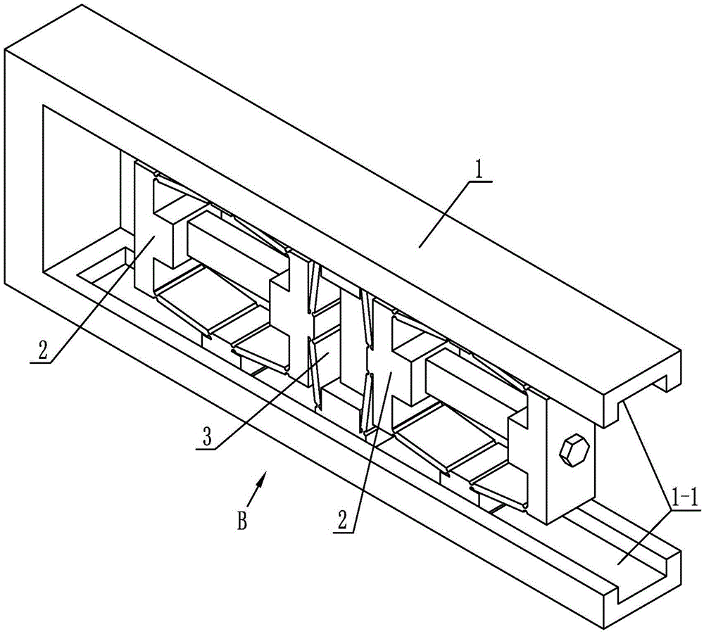
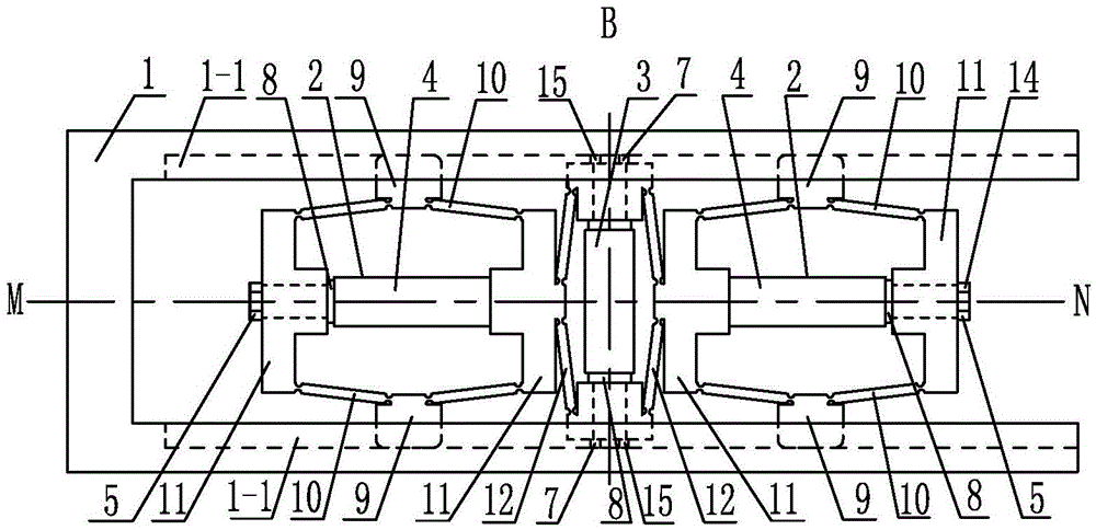
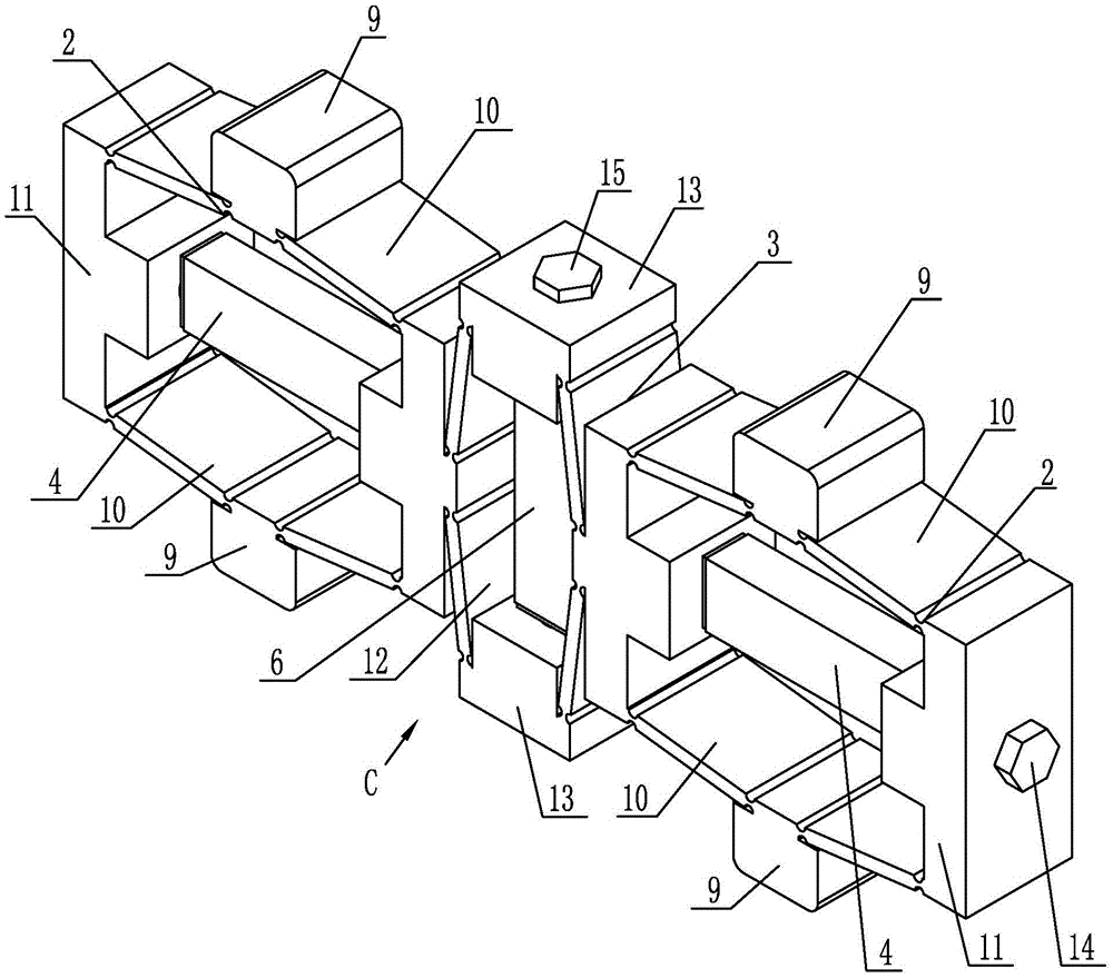
[0011] Specific implementation mode one: combine Figure 1-Figure 5 Illustrate that an internally driven passive clamping piezoelectric driver of this embodiment includes a guide rail 1, a driving body 3, a driving piezoelectric stack 6, two clamping piezoelectric stacks 4 and two clamping bodies 2; the guide rail 1 is a П-shaped guide rail, and the two arms of the guide rail 1 are set horizontally;

[0012] Each clamping body 2 includes a clamping piezoelectric stack pretensioner 5, two flexible hinges 10 for clamping triangular amplification, two clamping piezoelectric stack supports 11 and two clamping heads 9; The clamping triangle enlarged flexible hinge 10 is arranged symmetrically with the center line MN of the guide rail 1, and the middle parts of the two clamping triangle enlarged flexible hinges 10 are each equipped with a clamping head 9, and the two clamping triangle enlarged flexible hinges 10 A clamp piezoelectric stack support body 11 is installed at both ends,...

specific Embodiment approach 2

[0015] Specific implementation mode two: combination figure 2 Note that each flexible hinge 10 with enlarged clamping triangle in this embodiment is a straight circular flexible hinge with enlarged triangle clamping, and a clamping head 9 is connected to the outside of the central circular segment of each flexible hinge 10 with enlarged clamping triangle. Such arrangement has a compact structure, can be used in different occasions, can achieve precise resolution, high motion accuracy, and has good dynamic characteristics, which can greatly reduce the processing accuracy requirements of guide rails and clamping bodies. Others are the same as in the first embodiment.

specific Embodiment approach 3

[0016] Specific implementation mode three: combination figure 2 Note that each flexible hinge 12 driven by triangular enlargement in this embodiment is a straight circular flexible hinge driven by triangular enlargement. The stack supports 11 are connected. Such setting improves the walking speed of the driver, achieves precise resolution and high motion precision. Others are the same as in the first or second embodiment.


PUM


Abstract

An internally driven passive clamp piezoelectric driver, which relates to a piezoelectric driver, to solve the problem that the existing internally driven clamp piezoelectric driver cannot be self-locked when power is off, and the movement speed of the driver is slow. The machining precision of the guide rail requires high precision, which includes a guide rail, a driving body, a driving piezoelectric stack, two clamping piezoelectric stacks and two clamping bodies; each clamping body includes a clamping piezoelectric stack Stack pretensioner, two flexible hinges for clamping triangular amplification, two clamping piezoelectric stack supports and two clamping heads; each driving body includes two flexible hinges for driving delta amplification, two driving pressure The electric stack support body and two driving piezoelectric stack pretensioners; the driving body connected to the two clamping bodies is arranged between the two clamping bodies; the driving body and the two clamping bodies are arranged in the grooves of the two arms of the guide rail Inside. The invention is used in the process of micro-driving.

Description

technical field [0001] The invention relates to a piezoelectric driver, in particular to a passive clamp piezoelectric driver. Background technique [0002] Piezoelectric drive is a driving method widely used in the world at present, and it is mainly divided into resonant piezoelectric drive and non-resonant piezoelectric drive. The most widely used non-resonant piezoelectric driver is the clamped piezoelectric driver. This driver is a micro-drive device that uses the piezoelectric stack to energize and elongate to clamp and relax the guide rail, and then realizes the drive. Its working principle is similar to that of creeping reptiles, so it is also commonly referred to as inchworm or peristaltic piezo actuator. It is mainly used in the environment of large output force, precise positioning and low speed operation. At present, there are relatively many researches on resonant piezoelectric drive devices in China and have been applied to a certain extent, while there are re...

Claims


Application Information

Patent Timeline
Patent Type & Authority Patents(China)
IPC IPC(8): H02N2/02
Inventor 曲建俊李将郭文峰
Owner HARBIN INST OF TECH
Why Eureka
Try Eureka