Rapid clamping device

A clamping device and fast technology, applied in the direction of workpiece clamping device, positioning device, clamping, etc., can solve the problems of cumbersome operation, poor synchronization and low efficiency, and achieve the effect of compact size, high synchronization and high efficiency

Active Publication Date: 2018-06-15
SHENYANG INST OF AUTOMATION - CHINESE ACAD OF SCI
View PDF7 Cites 8 Cited by
  • Summary
  • Abstract
  • Description
  • Claims
  • Application Information

AI Technical Summary

Problems solved by technology

[0003] The existing clamping device generally realizes the fixation of the clamped parts through the clamping parts on both sides and the screws and nuts uniformly distributed along the circumference. Low, and poor synchronization during loading

Method used


Image

  • Rapid clamping device
  • Rapid clamping device
  • Rapid clamping device

Examples


Embodiment Construction

[0023] The present invention will be described in further detail below in conjunction with the accompanying drawings.

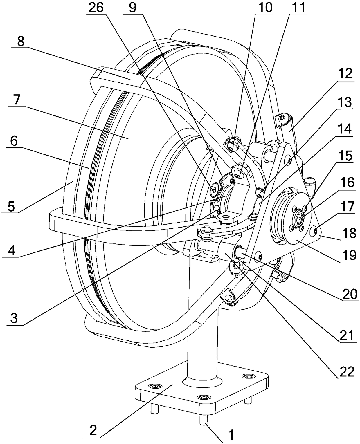
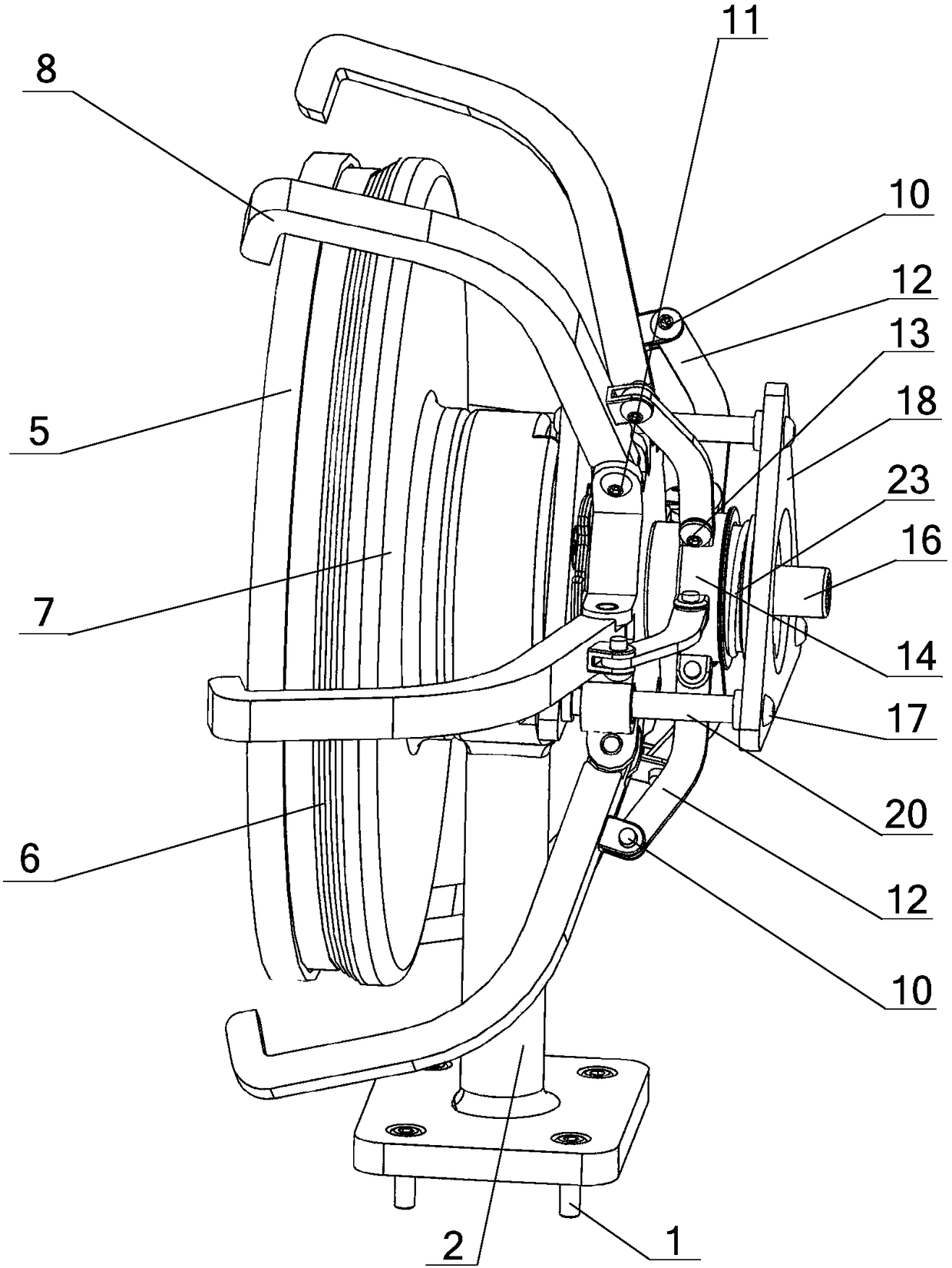
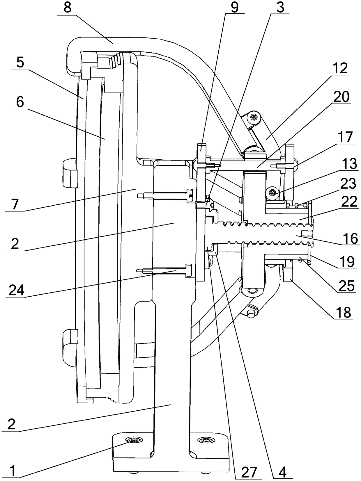
[0024] Such as Figure 1~3 As shown, the present invention includes a bracket 2, a push rod end cover 4, a compression end ring 5, a compression flange 7, a pull rod 8, a top plate 9, a connecting rod 12, a synchronous slip ring 14, a push rod 16, a cover plate 18, Copper sleeve flange 19, guide shaft 20, graphite copper sleeve 21 and central pressing member 22, wherein the pressing flange 7 and the top plate 9 are installed on the upper part of the bracket 2 through the pressing flange fixing screw 24 and the top plate fixing screw 26 respectively. On both sides, the lower part of the bracket 2 is provided with bracket fixing screws 1 for connection and installation.

[0025] One end of the ejector rod 16 is provided with a boss flange 27, and the boss flange 27 is accommodated in the ejector rod end cover 4, and the ejector rod end cover 4 is fixed on the ...


PUM


Abstract

The invention relates to a rapid clamping device. A pressing flange and a top plate are arranged on the two sides of a support respectively, one end of an ejector rod is rotationally connected with the top plate, the other end of the ejector rod is in threaded connection with a center pressing piece, a sliding ring copper sleeve sleeves the center pressing piece, a synchronous sliding ring which moves oppositely sleeves outside the sliding ring copper sleeve, a copper sleeve flange is arranged at the outer end of the sliding ring copper sleeve, a spring which sleeves the sliding ring copper sleeve is arranged between the synchronous sliding ring and the copper sleeve flange, and the two ends of the spring are respectively abutted against the synchronous sliding ring and the copper sleeve flange; the number of pull rods is multiple, the pull rods are uniformly distributed in the circumferential direction of clamping parts, one end of each pulling rod is hinged to the center pressing piece, the other end of each pulling rod is a pressing end, and the clamped parts are located between the compression flange and the compression ends of the pull rods; and connecting rods are connectedbetween each pull rod and the synchronous sliding ring, and the two ends of the connecting rod are respectively hinged to the pull rods and the synchronous sliding ring. The device has the advantagesof being novel in structure, simple and convenient to operate, small in size and the like.

Description

technical field [0001] The invention relates to a clamping device, in particular to a quick clamping device capable of realizing multi-point synchronous clamping around the periphery. Background technique [0002] In recent years, with the rapid development of industrial automation, the requirements for production efficiency are getting higher and higher; in order to meet people's requirements for ease of operation in the work and production process, the quick clamping device is easy to operate, reliable clamping and Features such as high synchronization have gradually become research hotspots in the field of automation in various countries. [0003] The existing clamping device generally realizes the fixation of the clamped parts through the clamping parts on both sides and the screws and nuts evenly distributed along the circumference. Low, and poor synchronization during loading. Contents of the invention [0004] In view of the above-mentioned problems existing in th...

Claims


Application Information

Patent Timeline
Patent Type & Authority Applications(China)
IPC IPC(8): B25B11/00
CPCB25B11/00B25B5/02B25B5/04B25B5/10B25B5/14B23Q3/12B25B11/02
Inventor 刘金国陈科利迟浩东佟操
Owner SHENYANG INST OF AUTOMATION - CHINESE ACAD OF SCI
Why Eureka
Try Eureka