Eureka AIR delivers breakthrough ideas for toughest innovation challenges, trusted by R&D personnel around the world.

A video signal frame synchronization method and device thereof

A video signal and frame synchronization technology, which is applied in the direction of image communication, selective content distribution, electrical components, etc., can solve the problems of video image quality damage, fragmentation, and inability to match, and achieve the lossless image quality of each frame of the new video signal , to avoid the effect of fragmentation

Active Publication Date: 2017-12-15
ZHEJIANG UNIV
View PDF4 Cites 0 Cited by
  • Summary
  • Abstract
  • Description
  • Claims
  • Application Information

AI Technical Summary

Problems solved by technology

When ping-pong buffering is used between the original video signal and the new video signal, if the frame period between the original video signal and the new video signal is different, as the frame period difference gradually accumulates, it is very likely that for the new video signal In a certain frame of the picture, each pixel of the picture comes from two different pictures before and after the original video signal, which causes this frame of the new video signal to display part of the content of the two original video pictures at the same time, which cannot be matched, resulting in serious The sense of fragmentation, the quality of the video picture is damaged
If more caches are used, such as three sets of buffers, each frame of the original video data is cached in sequence, so that the readout operation of the original video will have a greater time margin, and the frame skipping read Or measures such as repeatedly reading the current frame can make each pixel in any frame of the new video signal come from a corresponding frame in the original video, thereby eliminating the sense of fragmentation in each frame of the new video signal, but due to The accumulated frame cycle difference still exists, and the method of skipping frame reading or repeatedly reading the current frame will cause frame skipping or freezing in the new video screen, and the quality of the video screen will also be damaged

Method used


Image

  • A video signal frame synchronization method and device thereof
  • A video signal frame synchronization method and device thereof
  • A video signal frame synchronization method and device thereof

Examples


Embodiment Construction

[0025] The present invention will be described in further detail below in conjunction with the embodiments and accompanying drawings, but the embodiments of the present invention are not limited thereto.

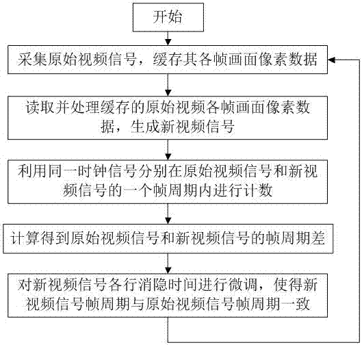
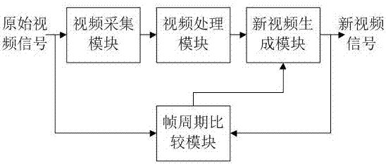
[0026] The flow of the video frame synchronization method in this embodiment is as follows: figure 1 As shown, it is possible to use the figure 2 The video frame synchronization device shown is implemented.

[0027] In this embodiment, the resolution of the original video signal is 1024×768, and each frame of the original video signal is interpolated and enlarged to obtain a new video signal with a resolution of 1920×1080, and the new video signal uses a clock signal output by an independent crystal oscillator As its pixel clock signal, the period of the clock signal output by the crystal oscillator has an error tolerance range and cannot be perfectly accurate. Therefore, the original video signal and the new video signal have different resolutions and pixel clock signals...


PUM


Abstract

The invention discloses a video signal frame synchronization method and device. The method comprises the steps that (1) original video signals are collected, and various frame image pixel data are cached; (2) the cached original video various frame image pixel data are read and processed, and new video signals are generated; (3) computing is carried out in frame cycles, of the original video signals and the new video signals, where the same clock signals are placed; (4) frame cycle difference of the original video signals and the new video signals is obtained by computing; and (5) each row of blanking time of the new video signals is subjected to fine tuning, so that a new video signal frame cycle is identical to an original video signal frame cycle. The invention further discloses the video signal frame synchronization device. Under the situation that an original video caching method and a cache number are not changed, the frame cycles of the new video signals and the original video signals are subjected to synchronization, the phenomena such as new video signal image isolating, frame skipping and blocking are avoided, and the fact that various frame image quality of the new video signals is not damaged is guaranteed.

Description

technical field [0001] The invention relates to the field of video signal processing, in particular to a video signal frame synchronization method and a device thereof. Background technique [0002] Generally speaking, a video signal is composed of several frames of images transmitted continuously, and each frame of images is composed of pixels in several rows and columns. The transmission time of each frame is called the frame period, and the transmission time of each pixel is called the pixel period. [0003] The display of the video screen by the monitor is realized in the form of scanning, and the scanning always starts from the upper left corner of the screen and moves forward horizontally. When the scanning point reaches the right edge of the screen, the scanning point quickly returns to the left, and starts to scan the next line below the starting point of the previous line. The returning process between lines is called horizontal blanking. After the scanning point ...

Claims


Application Information

Patent Timeline
Patent Type & Authority Patents(China)
IPC IPC(8): H04N21/23
Inventor 王明宇韩雁王锐
Owner ZHEJIANG UNIV
Why Eureka
Eureka Blog
Learn More