cutting device

A cutting device and cutting tool technology, applied in glass cutting devices, fine working devices, manufacturing tools, etc., can solve the problems of glass sheet peeling, glass plate cracks, weakening of the cracking effect, etc., to achieve accurate and stable cutting, The effect of preventing the occurrence of cracks

Inactive Publication Date: 2012-02-08
TAKITA RES & DEV
View PDF7 Cites 0 Cited by
  • Summary
  • Abstract
  • Description
  • Claims
  • Application Information

AI Technical Summary

Problems solved by technology

That is, in the technology of Patent Document 1, when the rubber is pressed from the opposite surface of the cutting groove, the glass substrate is impacted, and the glass plate is affected by the impact, and cracks or cracks are likely to occur, or the electric wire is cut, etc., thereby reducing the Quality of glass plate products
[0017] In the technology of Patent Document 2, it is difficult to control the development direction of the cut marks, which causes cracks inside the glass plate, resulting in poor product quality
[0018] In the technologies of Patent Document 3 and Patent Document 4, since the irradiation output of the laser beam must be increased, the inclination of the cutting groove will be affected, resulting in cracks in the inward direction of the glass plate, or peeling of the glass sheet along the cutting groove. Cracks and other phenomena, and reduce the performance of glass plate products
[0019] In addition, in the technology of Patent Document 3, when the crack is guided along the path of the laser beam, the split crack will develop along the moving path of the laser beam irradiation position, which may affect the processing accuracy.
[0020] Furthermore, in the technology of Patent Document 4, when a laser beam is irradiated, local concentrated stress is generated by the rapid temperature change between the center and the periphery of the beam. There are many factors such as the light absorption rate in the medium, so that the thermal stress (tensile stress) is concentrated and destroyed, or when the local concentrated stress fails to exceed the allowable stress of the material, there may even be a problem of weakening the initial cracking effect
In addition, similar to the technology of Patent Document 3, when cracks are guided, additional cracks will develop following the moving path of the laser beam irradiation position, resulting in a problem of poor processing accuracy.
[0021] In the technique of Patent Document 5, before drilling or cutting the processed part by laser irradiation, it is necessary to perform a thinning process in advance to make the processed part thinner than other parts. stamping machine, but there is a problem of increasing manufacturing costs
[0022] In the technologies of Patent Document 6 and Patent Document 7, since complex devices such as laser equipment and required optical peripheral equipment must be formed, and the cost of the equipment is very high, there is a problem that the cost is extremely high

Method used


Image

  • cutting device
  • cutting device
  • cutting device

Examples


Embodiment Construction

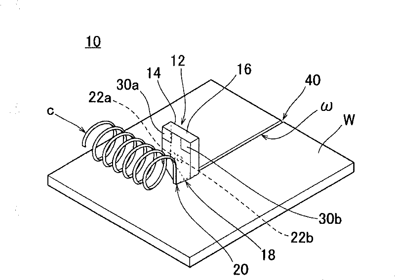
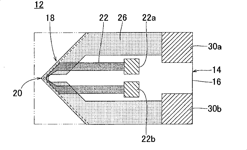
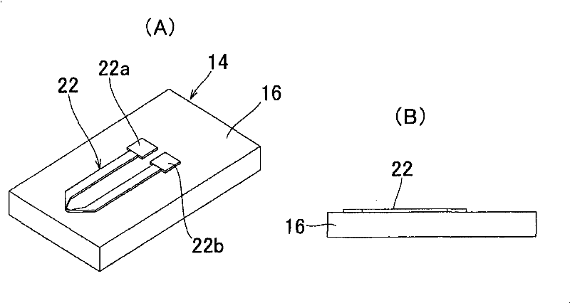
[0082] figure 1 It is a perspective view of main parts showing an example of an embodiment of the cutting device of the present invention, figure 2 for illustrative purposes only figure 1 A plan view of an example of the cutting tool of the embodiment. The cutting device of the present invention is suitable for cutting brittle materials such as optical glass, quartz glass and other glass, ceramics, silicon crystal (silicon), semiconductor materials, etc. A preferable cutting device 10 such as cutting a glass plate in the panel manufacturing process of a display will be described.

[0083] The cutting device 10 includes a cutting tool 12 . For example figure 1 As shown, the cutting tool 12 is disposed so as to be in contact with a predetermined cutting portion ω (referred to as “cutting portion ω” in a narrow sense) of a workpiece (processed object) such as a rectangular glass plate W. Roughly speaking, the cutting tool 10 speeds up the glass sheet W to a high temperature...


PUM


Abstract

The invention provides a cutting device, which can prevent cracks from occurring, without compromising the quality of the cut object, so as to cut the cut object accurately and stably. The cutting device 10 is used to cut the cut object W formed by brittle materials such as glass, ceramics, semiconductor materials, etc., and it includes: a cutting tool 12, which is configured to contact the desired cutting position ω of the cut object; a displacement mechanism , which is used to generate relative movement between the cutting tool 12 and the object W along the cutting portion ω, the cutting tool 12 includes: a blade portion 18, which has a tip portion 20 (edge ​​portion) for cutting the object W The heating element heats the blade portion 18 at a high temperature above the softening point of the object W to be cut, and through the displacement mechanism, relative motion is generated between the object W to be cut and the tip portion 20 heated by the heating element, thereby to the object to be cut The cutting part ω of the cutting object W performs cutting cutting.

Description

technical field [0001] The present invention relates to a cutting device, which is suitable for cutting objects to be cut formed of brittle materials such as glass and ceramics, especially thin plates, especially glass used in the manufacturing process of liquid crystal and plasma displays, for example. Substrate cutting. Background technique [0002] As the prior art which is the background of the invention of the present application, there is a cutting method of a bonded glass substrate, which is characterized in that on a bonded glass plate formed by bonding two glass substrates, a rubber is pressed from the opposite side of the cutting groove. plate, etc., the cutting groove is formed with a glass cutting tool such as a cemented carbide cutter wheel, and pressure is applied along the scribe line to cause vertical cracks in the cutting groove to separate the glass substrate. (For example, refer to Patent Document 1) [0003] In addition, as the prior art of the backgrou...

Claims


Application Information

Patent Timeline
Patent Type & Authority Patents(China)
IPC IPC(8): B28D5/04C03B33/10C03B33/023
CPCB28D1/221
Inventor 田北正昭
Owner TAKITA RES & DEV
Why Eureka
Try Eureka