Chain plate type baking tunnel furnace

A tunnel furnace and chain plate technology, which is applied in the fields of baking, food oven, food science, etc., can solve the problems of steel belt deviation, unfavorable production cost, troublesome users, etc., to ensure long-term stable operation and improve production Efficiency, the effect of avoiding stuck

Active Publication Date: 2014-12-03
GUANGZHOU FUYA MACHINERY
View PDF5 Cites 5 Cited by
  • Summary
  • Abstract
  • Description
  • Claims
  • Application Information

AI Technical Summary

Problems solved by technology

[0003] 1. Chain plate type tunnel furnace, the chain plate 80 is shaped (such as figure 1 and figure 2 shown), the gap 81 between the chain plate 80 and the chain plate 80 is too large, especially when the chain plate 80 passes through the driving sprocket 82, the gap 81 is larger, so the chain plate 80 of this chain plate type tunnel furnace It is necessary to put the baking tray to bake the product, otherwise the product will be damaged by the chain plate 80, and the configuration of the baking tray itself is not conducive to saving production costs, and the product will be released from the baking tray after baking. trouble;
[0004] 2. Mesh belt tunnel furnace, due to the large mesh, the embryos of products such as cakes and bread will leak along the mesh (this type of tunnel furnace is suitable for the drying industry), and the dense mesh belt is not conducive to cleaning (this type of tunnel furnace is suitable for drying) The product is suitable for the biscuit industry);
[0005] 3. Steel belt tunnel furnace, the steel belt tunnel furnace can directly put raw materials, but the steel belt of the steel belt furnace is easy to deviate during operation, and the operation is unstable; the transmission hub of the steel belt furnace is large, requires high precision, and is difficult to process Large, and the cost of the steel belt is too high

Method used


Image

  • Chain plate type baking tunnel furnace
  • Chain plate type baking tunnel furnace
  • Chain plate type baking tunnel furnace

Examples


Embodiment Construction

[0023] Below, in conjunction with accompanying drawing and specific embodiment, the present invention is described further:

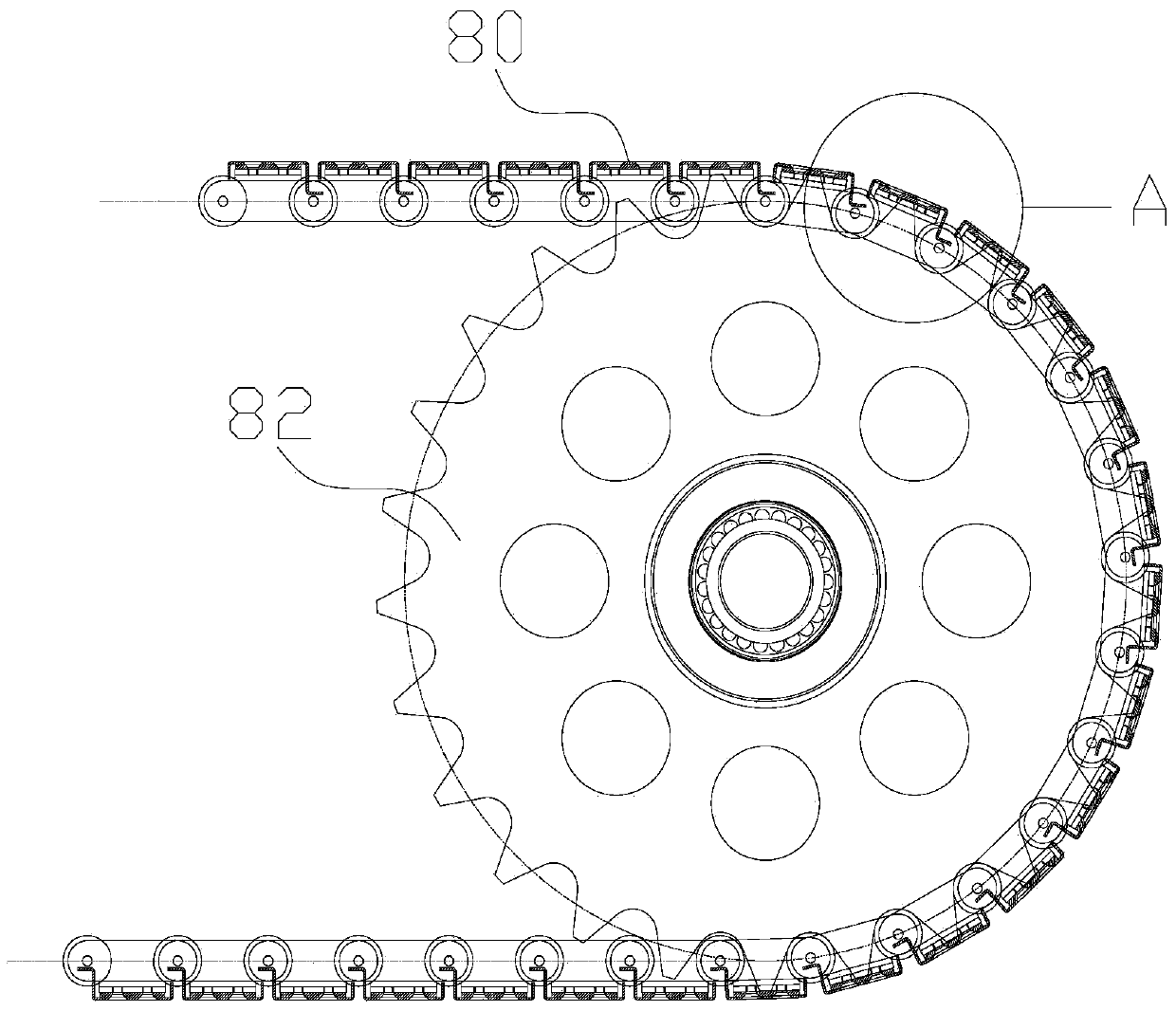
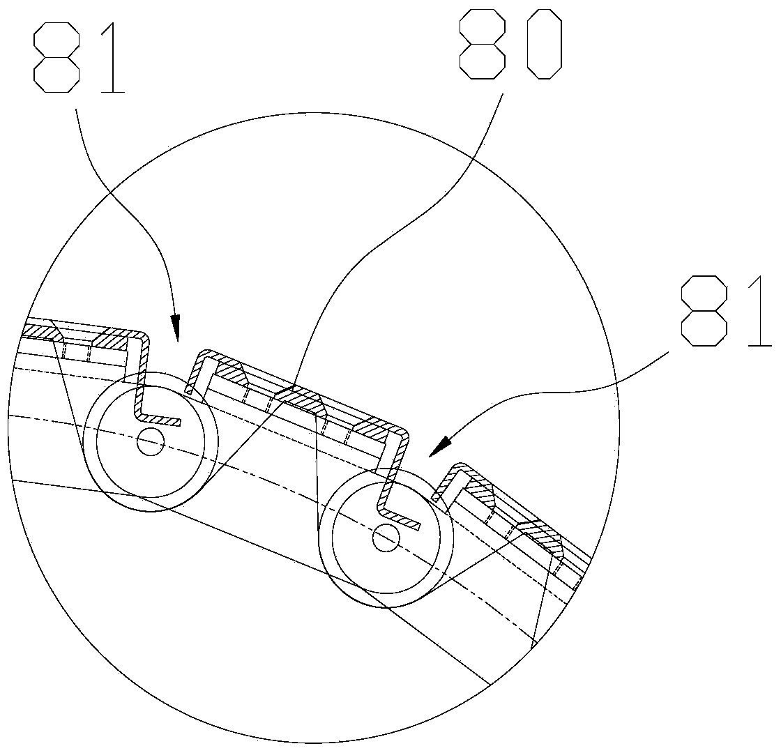
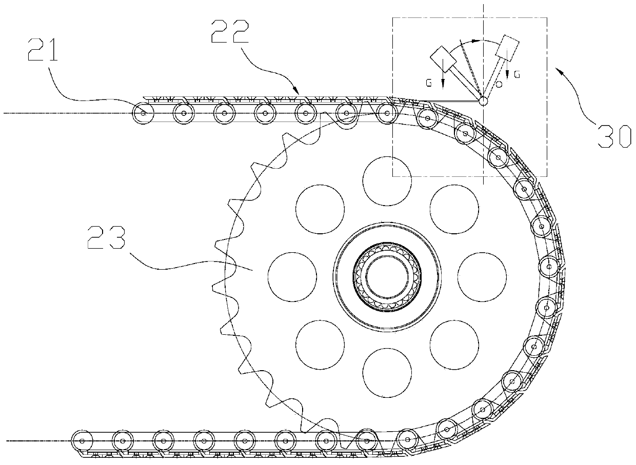
[0024] see Figure 3 to Figure 6 , which is a chain-plate type baking tunnel furnace of the present invention, comprising a cabinet (not shown) with a baking channel, a conveying device and a heating device (not shown) arranged in the cabinet, the cabinet is designed to There is a box body with an input end and an output end, and the space in the box forms the baking channel; the heating device is used to heat the air in the cabinet; the transmission device includes a transmission chain 21, which is fixed outside the transmission chain 21 The chain plate belt 22 on the surface and the drive sprocket 23 that is connected with the transmission chain 21 and is used to provide traction. The chain plate belt 22 is made up of a plurality of chain plates 221 arranged side by side along the length direction of the transmission chain 21. The chain plate 221 inc...


PUM


Abstract

The invention discloses a chain plate type baking tunnel furnace comprising a case, and a conveying device and a heating device which are arranged in the case. The conveying device comprises a conveying chain, a chain plate belt and a drive sprocket. The chain plate belt comprises a plurality of chain plates comprising elongated main plates and inclined plates formed by bending the edges of the front ends of the main plates at the certain angles. The inclined plates extend below the tail ends of the front chain plates. The furnace further comprises a material fetching device arranged at the outlet of a baking channel; the material fetching device comprises a scraping blade pivoted to the case in a manner of vertical overturning and a tension mechanism, and the tension mechanism is used for controlling the scraping blade to overturn between a first position fitted to the chain plates and a second position separated from the chain plates. The chain plates are ingenious in structural design, the clearances between the chain plates are reduced, a baking plate is omitted, and the manufacture cost can be saved; by arranging the material fetching device, the producing efficiency can be improved, and the chain plate type baking tunnel furnace has the advantages of stable operation.

Description

technical field [0001] The invention relates to the field of baking tunnel furnaces, in particular to a chain plate type baking tunnel furnace in which raw materials can be directly placed on chain plates for baking. Background technique [0002] In the production process of food such as bread and cakes, an oven is usually used to bake the raw material until it is cooked. The existing ovens generally have the following types: [0003] 1. Chain plate type tunnel furnace, the chain plate 80 is shaped (such as figure 1 and figure 2 shown), the gap 81 between the chain plate 80 and the chain plate 80 is too large, especially when the chain plate 80 passes through the driving sprocket 82, the gap 81 is larger, so the chain plate 80 of this chain plate type tunnel furnace It is necessary to put the baking tray to bake the product, otherwise the product will be damaged by the chain plate 80, and the configuration of the baking tray itself is not conducive to saving production co...

Claims


Application Information

Patent Timeline
Patent Type & Authority Applications(China)
IPC IPC(8): A21B1/48A21B3/00
Inventor 付文兵程应科
Owner GUANGZHOU FUYA MACHINERY
Why Eureka
Try Eureka