

Fluid filtering method and device
A technology of filtering device and filtering method, applied in the fields of filtering separation, separation method, chemical instrument and method, etc., can solve the problems of complex structure, high cost, poor cleaning effect, etc., and achieve good cleaning effect, simple structure and easy maintenance. Effect
- Summary
- Abstract
- Description
- Claims
- Application Information
AI Technical Summary
Problems solved by technology
Method used
Image

Examples
Embodiment 1
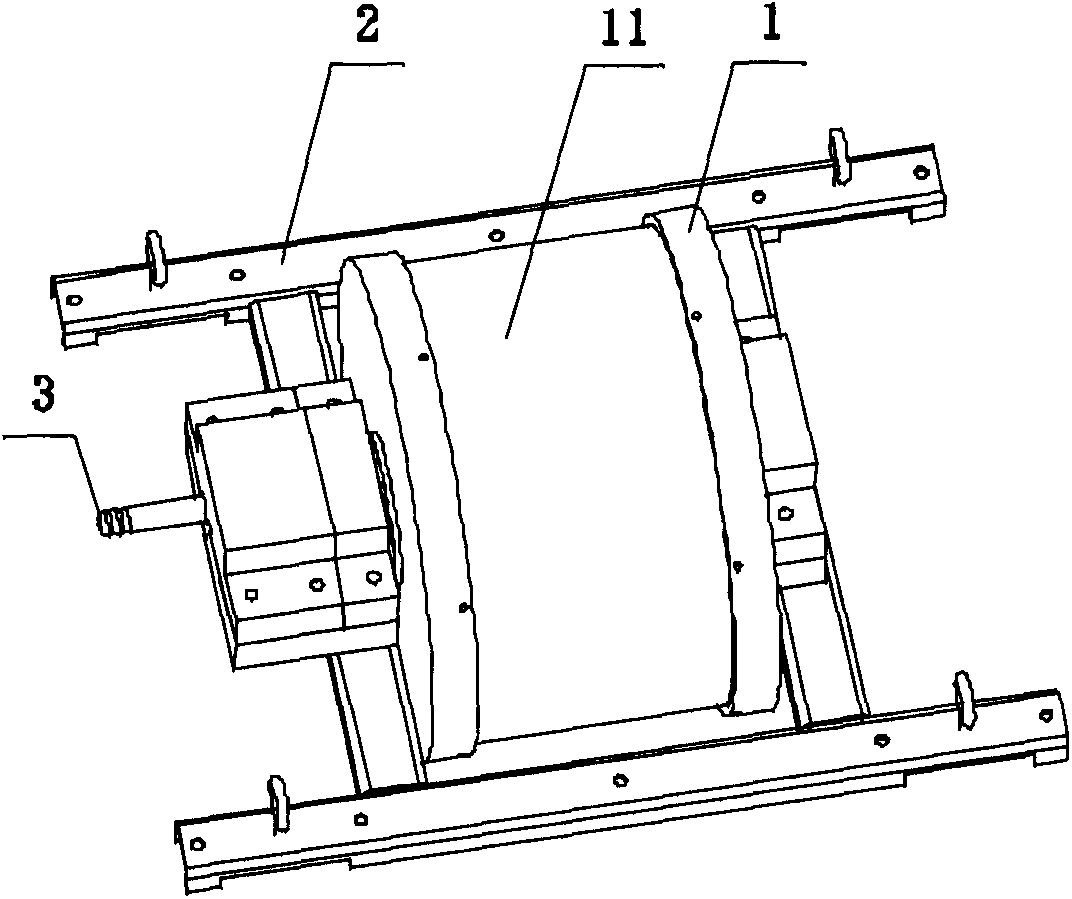
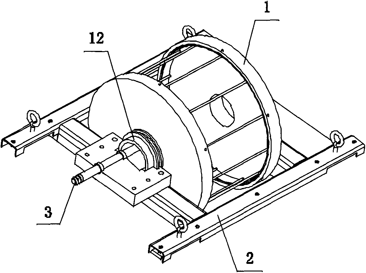
[0047] Such as figure 1 , figure 2 , Figure 10 As shown, a fluid filter device is used in the filtration of sewage 7 with a high flow rate, comprising a rotating shaft 12, a cylindrical part 1 (such as a squirrel cage) fixed on the rotating shaft 12, and driving the cylindrical part 1 to rotate The power source, the first tube 3 and the bracket 2.
[0048] The cylindrical part 1 is cylindrical, and a filter screen 11 is arranged on the outer surface; the two ends of the cylindrical part 1 are installed on the rotating shaft 12, and one end of the rotating shaft 12 is hollow and installed on the bracket 2, the rotating shaft 12 and the cylindrical part 1 rotate together on the support 2, and the support 2 is installed in the sewage tank. A part of the cylindrical part 1 below the rotating shaft 12 is placed under the water surface of the sewage 7 . One end of the first tube 3 extends into the cylindrical part 1 for extracting filtered water samples; the other end passes t...
Embodiment 2
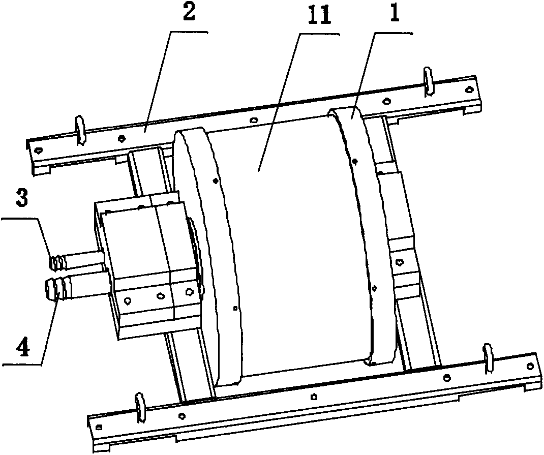
[0055] Such as image 3 , Figure 4 , Figure 11 As shown, a fluid filter device is used in the filtration of sewage 7 with a higher flow rate. The difference from the filter device in Example 1 is:
[0056] The filtering device also includes a second pipe 4, one end of the second pipe 4 extends into the cylindrical part 1, and several outlets 41 are arranged on it, and the direction of the outlets 41 is along the The cylindrical part 1 is in a non-radial tangential direction; the other end of the second tube 4 passes through the inside of the rotating shaft 12 and is fixed on the bracket 2 .
[0057] The fluid filtering method of the embodiment of the present invention, that is, the working process of the above-mentioned filtering device, the fluid filtering method includes the following steps:
[0058] (A1) The flowing sewage 7 drives the cylindrical part 1, so that the cylindrical part 1 rotates on the support, and a part of the cylindrical part 1 below the rotating shaf...
Embodiment 3
[0064] Such as Figure 5 , Figure 6 and Figure 10 As shown, a fluid filter device is used in the filtration of sewage 7 with a high flow rate, and the difference from the filter device in Example 1 is:
[0065] The filtering device also includes floating objects 5 and fixtures on the water surface of the sewage 7, and the support 2 is installed on the floating objects 5, such as buoys, so that the cylindrical part 1 floats on the water surface, and along with The water surface of the sewage 7 is raised and lowered; the fixed part is a rope, which is used to prevent the flowing sewage 7 from washing away the cylindrical part 1 floating on the water surface.
[0066] The fluid filtering method of the embodiment of the present invention, that is, the working process of the above-mentioned filtering device, the fluid filtering method includes the following steps:
[0067] (A1) The flowing sewage 7 drives the cylindrical part 1, so that the cylindrical part 1 rotates on the su...
PUM
 Abstract
Description
Claims
Application Information