Combined sliding wheel for hole grinding processing of cylinder body and manufacturing method of combined sliding wheel

A manufacturing method and a combined wheel technology are applied in metal processing equipment, machine tools designed for grinding workpiece rotating surfaces, grinders, etc., which can solve the problems of restricting the movement of the mechanism, low safety performance, large overall size, etc. The effect of space size, reasonable structure design and convenient production and processing

Inactive Publication Date: 2014-12-03
WUHU HENGKUN AUTO PARTS
View PDF6 Cites 0 Cited by
  • Summary
  • Abstract
  • Description
  • Claims
  • Application Information

AI Technical Summary

Problems solved by technology

For the first type of motion, the workpiece is installed on a single-degree-of-freedom motion platform or a two-degree-of-freedom motion platform. The principles of these motion platforms mostly use the motor to directly drive the screw mechanism to achieve single-degree of freedom or two-degree-of-freedom. The movement, the structural connection is relatively simple, but since the motor needs to be arranged at both ends of the axial position of the screw mechanism, it will occupy a large space volume, making the overall size larger and restricting the movement of the mechanism. At the same time, due to the large exposed parts of the platform as a whole, the safety performance is low during the movement of the platform, and it is easy to touch the staff, which poses a threat to the personal safety of the staff.

Method used


Image

  • Combined sliding wheel for hole grinding processing of cylinder body and manufacturing method of combined sliding wheel
  • Combined sliding wheel for hole grinding processing of cylinder body and manufacturing method of combined sliding wheel
  • Combined sliding wheel for hole grinding processing of cylinder body and manufacturing method of combined sliding wheel

Examples


Embodiment Construction

[0042] In order to make the technical means, creative features, goals and effects achieved by the present invention easy to understand, the present invention will be further elaborated below.

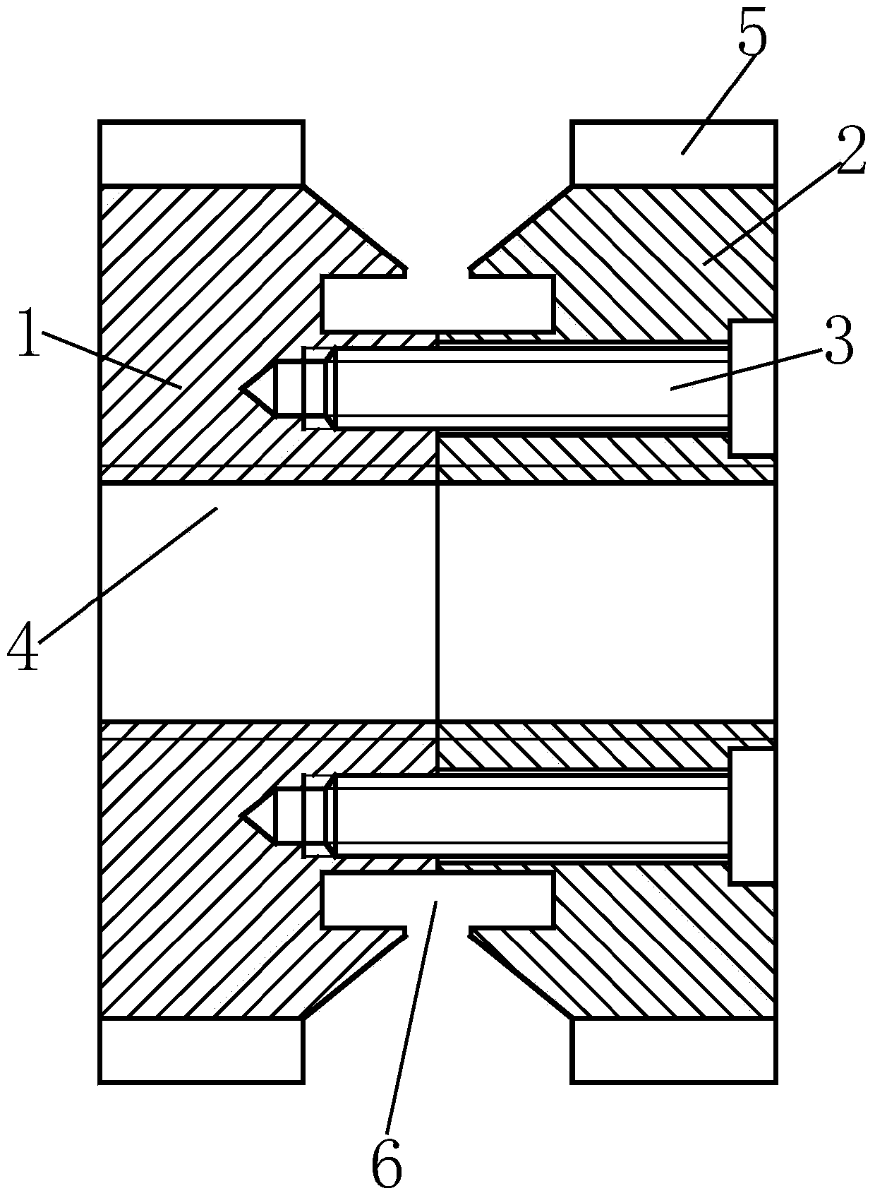
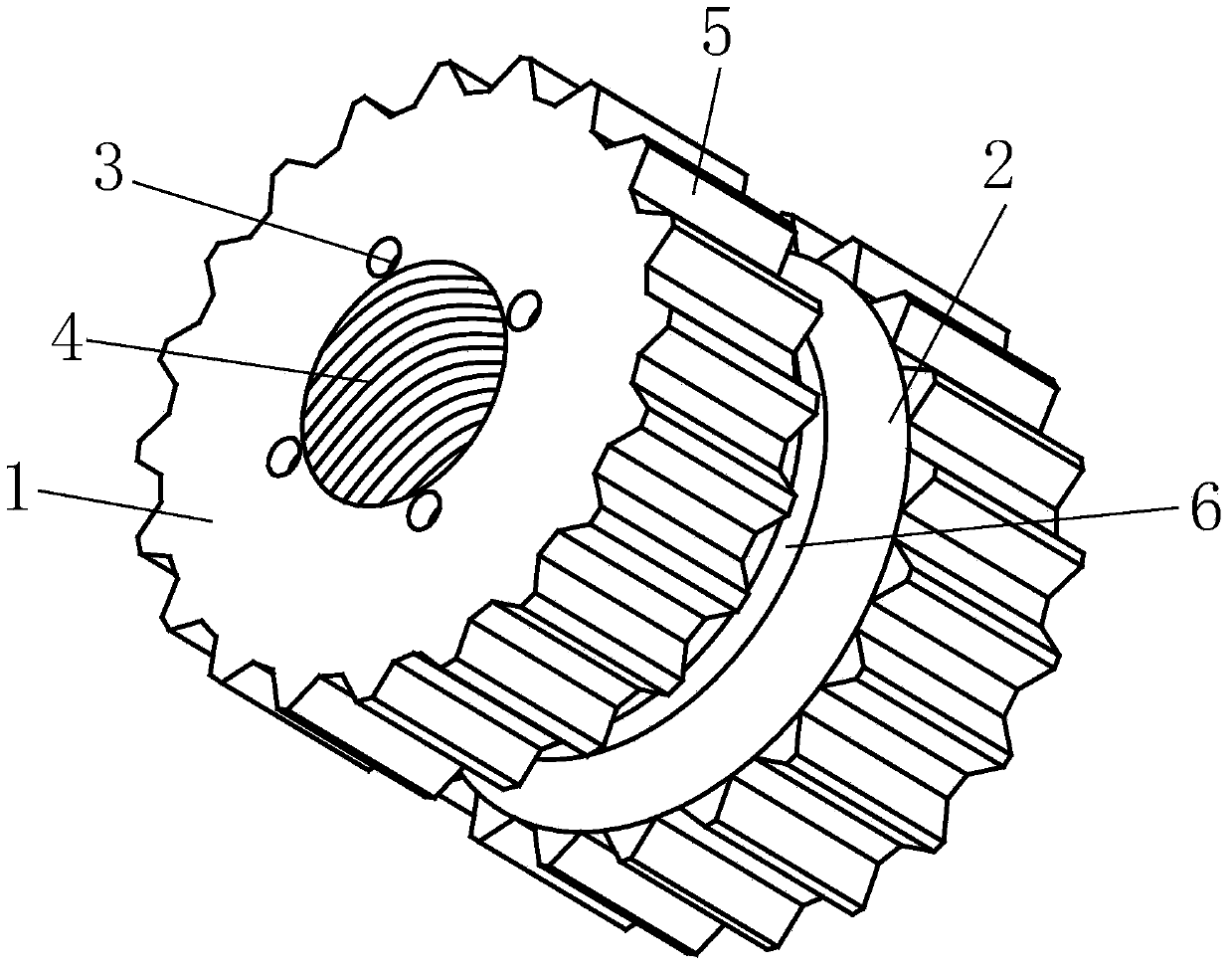
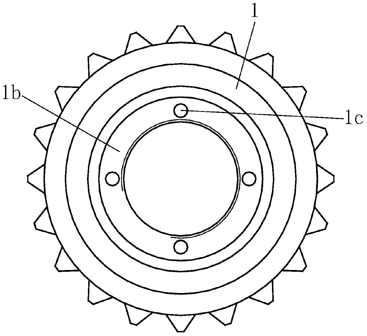
[0043] Such as Figure 1 to Figure 9 As shown, a sliding combination wheel for cylinder grinding hole processing includes a left wheel body 1, a right wheel body 2 and a counterbore screw 3, the end faces of the left wheel body 1 and the right wheel body 2 are bonded, and the left wheel body Body 1 and right wheel body 2 are fixedly connected by countersunk screws 3, and the middle parts of said left wheel body 1 and right wheel body 2 are provided with threaded connection holes 4, and the outer circular surfaces of said left wheel body 1 and right wheel body 2 are Both are provided with ring teeth 5, and ring grooves 6 coaxial with threaded connection holes 4 are provided at the joints of the end faces of the left wheel body 1 and the right wheel body 2. The invention adopts a combine...


PUM


Abstract

The invention relates to a combined sliding wheel for hole grinding processing of a cylinder body and a manufacturing method of the combined sliding wheel. The combined sliding wheel comprises a left wheel body, a right wheel body and countersunk screws, wherein one end surface of the left wheel body and one end surface of the right wheel body are attached, the left wheel body and the right wheel body are fixedly connected through the countersunk screws, thread connection holes are formed in the middles of the left wheel part and the right wheel part, annular teeth are arranged on the excircle surfaces of the left wheel body and the right wheel body, and an annular groove which shares the same axis with the thread connection holes is formed in the end surface attaching position of the left wheel body and the right wheel body. The manufacturing method is as follows: 1), casting of a single part; 2), processing of separated parts; and 3), assembling processing. The combined sliding wheel and the manufacturing method have the advantages of reasonable structure design, convenience in production and processing and the like, power transmission is realized through meshing action of an external gear driven by a motor and the annular teeth, so that a single-DOF (degree of freedom) moving platform or a two-DOF moving platform moves, and the movement requirement for actual production processing is met; and with adoption of single-part processing and assembling processing combined manner, the structure feature and size can meet the matching requirement, and batch production processing is easy to realize.

Description

technical field [0001] The invention relates to an auxiliary part for grinding holes of a brake hydraulic cylinder, in particular to a sliding combination wheel for grinding holes of a cylinder body and a manufacturing method thereof. Background technique [0002] In the process of grinding the hole of the brake hydraulic cylinder with the grinding machine, there are usually two movement modes. The first is that the tool rotates and the workpiece is fed to complete the entire hole grinding process; the second is that the tool rotates. And feeding, the workpiece is still. For the first type of motion, the workpiece is installed on a single-degree-of-freedom motion platform or a two-degree-of-freedom motion platform. The principles of these motion platforms mostly use the motor to directly drive the screw mechanism to achieve single-degree of freedom or two-degree-of-freedom. The movement, the structural connection is relatively simple, but since the motor needs to be arrange...

Claims


Application Information

Patent Timeline
Patent Type & Authority Applications(China)
IPC IPC(8): B24B5/48B23P15/00
CPCB24B5/48B23P15/00
Inventor 夏坤财
Owner WUHU HENGKUN AUTO PARTS
Why Eureka
Try Eureka