Paper pressing mechanism for bookbinding machines

A technology of a paper pressing mechanism and a binding machine, which is applied in the direction of binding and the like, can solve the problems of cumbersome use, easy damage to the buffer mechanism, no service life, etc., and achieves the effects of simple structure, elimination of impact force, and good paper pressing effect.

Active Publication Date: 2014-12-03
ZHEJIANG ZHIYUAN OFFICE EQUIP MFG
View PDF7 Cites 4 Cited by
  • Summary
  • Abstract
  • Description
  • Claims
  • Application Information

AI Technical Summary

Problems solved by technology

The binding machine needs to press the paper tightly during the binding process, and then perform steps such as punching and binding. Because the reset of the paper pressing structure of the old-fashioned semi-automatic binding machine needs to be manually inconvenient, and the old-fashioned spring structure is prone to greater impact and noise. , the reset of the large impact is not good for the overall life of the structure, and the noise is easy to make people easily irritated in the binding work
[0003] For another example, the utility model patent application with the authorized announcement number of CN 201626181 U discloses a paper pressing structure for a binding machine, which solves the problem of the The technical problem of shortening the service life of the binding machine due to the insufficient reset mechanism of the paper pressing arm and the serious wear and tear, the technical solution adopted is that the structure includes a main frame with a fixed guide post, and a paper press that is slidably matched with the fixed guide post. arm and the matching return tension spring, and a return buffer mechanism positioned on the press arm is added to the press structure
However, this invention uses the spring as the main power source. If the spring tension is not large, the buffer mechanism will be easily stuck. If the spring tension is too large, the buffer mechanism will be easily damaged. Relatively speaking, the buffer mechanism needs the support of pulling force, so although this technical solution can alleviate certain impact and noise, it has no guarantee of service life, and there is no automatic device for reset while in use, which is cumbersome to use

Method used


Image

  • Paper pressing mechanism for bookbinding machines
  • Paper pressing mechanism for bookbinding machines

Examples


Embodiment Construction

[0024] The present invention will be further described below with reference to the accompanying drawings.

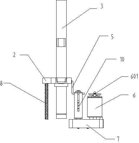
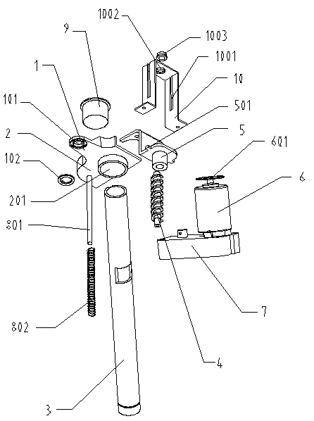
[0025] Such as Figures 1 to 2 As shown, the present embodiment includes a platen 1, a lifting bracket 2, a lifting spindle 3 for providing an action track for the lifting bracket 2, a lifting screw 4 for driving the lifting bracket 2 to move up and down, and a lifting screw 4 for fixing the lifting bracket 2. The screw guide bracket 5, the motor 6 for providing the action power of the lifting screw 4 and the gearbox 7 for adjusting the speed of the lifting screw 4; the lifting bracket 2 is socketed with the lifting main shaft 3, and the lifting bracket 2 is provided with The positioning hole 201, the lifting spindle 3 passes through the positioning hole 201 and is socketed with the lifting bracket 2, and the lifting spindle bushing 9 is arranged between the lifting spindle 3 and the lifting bracket 2. The platen 1 is fixed on the lifting bracket 2, the screw guide brac...


PUM


Abstract

The invention provides a paper pressing mechanism for bookbinding machines. The paper pressing mechanism is characterized in that a lifting perpendicularity degree guiding device is arranged on a lifting bracket and comprises a guiding strut and a balance spring, the guiding strut is arranged under the lifting bracket and used for adjusting of perpendicularity degree, the balance spring sleeves the guiding strut and used for balancing action force, generated from a lifting screw during the course of lifting, of the balance bracket and ensuring smoothness of lifting of the lifting bracket, and the guiding strut is parallel to a lifting spindle with each other. The paper pressing mechanism provided with an independent power is simple in structure, good in paper pressing effect and free of impact and noise during operation.

Description

technical field [0001] The invention relates to the field of binding machines, in particular to a paper pressing mechanism for the binding machine. Background technique [0002] A binding machine is a binding device that mechanically fixes paper with staples or hot melt adhesives, nylon tubes and other materials. According to different purposes, it can be divided into industrial binding machines and civilian binding machines, which are often used in printing factories, financial offices of enterprises and institutions, and file management. The binding machine needs to press the paper tightly during the binding process, and then perform steps such as punching and binding. Because the reset of the paper pressing structure of the old-fashioned semi-automatic binding machine needs to be manually inconvenient, and the old-fashioned spring structure is prone to greater impact and noise. , the reset of the big impact is unfavorable to the overall life of the structure, and the no...

Claims


Application Information

Patent Timeline
Patent Type & Authority Applications(China)
IPC IPC(8): B42B5/02
Inventor 阮永华谭显斌唐跃武
Owner ZHEJIANG ZHIYUAN OFFICE EQUIP MFG
Why Eureka
Try Eureka