Mounting structure for automobile auxiliary frame at front section of engine cabin boundary beam

A technology for the engine compartment and sub-frame, applied in the substructure, vehicle parts, transportation and packaging, etc., can solve problems such as attitude changes, bolt torsion attenuation, and impact on chassis performance, and achieve high performance levels and ensure strength and rigidity Effect

Active Publication Date: 2014-12-03
CHONGQING CHANGAN AUTOMOBILE CO LTD
View PDF8 Cites 4 Cited by
  • Summary
  • Abstract
  • Description
  • Claims
  • Application Information

AI Technical Summary

Problems solved by technology

The subframe installation structure of conventional models is as follows: Figure 5 , Image 6 As shown, the subframe assembly 10 is installed on the lower surface of the front section 9 of the side beam of the engine compartment, and the connection form is a bolt and nut connection. The structure of the subframe installation point 11 is a nut plate and a reinforcement plate. The torsion attenuation of the bolts at the installation point is prone to occur, and the assembly of the sub-frame is unreliable
If the stiffness and strength of the mounting point of the sub-frame is insufficient, the posture of the sub-frame in the vehicle coordinate system will change, which will affect the performance of the chassis

Method used


Image

  • Mounting structure for automobile auxiliary frame at front section of engine cabin boundary beam
  • Mounting structure for automobile auxiliary frame at front section of engine cabin boundary beam
  • Mounting structure for automobile auxiliary frame at front section of engine cabin boundary beam

Examples


Embodiment Construction

[0018] The present invention will be further described below in conjunction with the accompanying drawings.

[0019] As an important component of the chassis system, the sub-frame of the front rear drive vehicle is installed on the lower surface of the front section of the side beam of the engine compartment, and the matching parts are the front section of the side beam of the engine compartment (left and right).

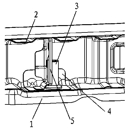
[0020] Such as figure 1 As shown, the present invention is made up of following several parts: engine compartment side beam front section 1, engine compartment side beam front section reinforcement 2, subframe installation threaded pipe 3, subframe installation nut plate 4 and thread pipe reinforcement plate 5.

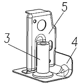
[0021] see figure 2 , The sub-frame installation threaded pipe 3 and the L-shaped sub-frame installation nut plate 4 are connected together by CO2 welding. The threaded pipe reinforcing plate 5 is a vertical plate, which is vertically attached t...


PUM


Abstract

The invention relates to a mounting structure for an automobile auxiliary frame at the front section of an engine cabin boundary beam. The mounting structure comprises the front section of the engine cabin boundary beam, an auxiliary frame mounting screwed pipe, an auxiliary frame mounting nut plate and a screwed pipe reinforcing plate. The three components of the auxiliary frame mounting screwed pipe, the auxiliary frame mounting nut plate and the screwed pipe reinforcing plate are mutually connected to form corners mutually, and are welded in reinforcing pieces together, and a reinforcing effect is formed in the X, Y and Z directions of the car body, so that the torsion of the mounting surface of an auxiliary frame during the running of the whole vehicle can be prevented, and torsion attenuation of mounting bolts of the auxiliary frame is prevented. Under the precondition that the function of structure installation is guaranteed, the mounting structure further has high strength value and high rigidity value of mounting point that a general structure cannot achieve.

Description

technical field [0001] The invention belongs to the technical field of automobile bodies, and relates to a sub-frame installation structure in the front section of an engine compartment side beam of a front-rear drive vehicle body. Background technique [0002] With the rapid development of the automobile industry and technology, automobile performance requires higher and higher rigidity of the body structure, [0003] As an important part of the suspension system and the body, the sub-frame of the front-rear drive model not only bears most of the weight of the engine assembly and suspension system, but also bears various impacts during driving. The subframe plays a particularly important role in the vehicle. The sub-frame not only has a particularly high strength and rigidity, but also the mounting points of the sub-frame on the body must also be sufficiently high in strength and rigidity. The subframe installation structure of conventional models is as follows: Figure 5...

Claims


Application Information

Patent Timeline
Patent Type & Authority Applications(China)
IPC IPC(8): B62D21/00
Inventor 车跃光
Owner CHONGQING CHANGAN AUTOMOBILE CO LTD
Why Eureka
Try Eureka