Vertical take-off and landing rotor aircraft with ducts built in wings

A rotorcraft and vertical take-off and landing technology, which is applied to aircraft, rotorcraft, motor vehicles, etc., can solve the problems of aircraft weight gain, the center of gravity of the whole machine can be adjusted in a small range, and the position of the center of gravity of passengers and cargo is high, so as to avoid exposed rotors, The effect of increasing the adjustable range and improving the propulsion efficiency

Active Publication Date: 2014-12-03
CHINA HELICOPTER RES & DEV INST
View PDF5 Cites 50 Cited by
  • Summary
  • Abstract
  • Description
  • Claims
  • Application Information

AI Technical Summary

Problems solved by technology

However, for aircraft with this structure, the propulsion device includes an engine and a reducer, and the weight is relatively large. In order to adjust the attitude of the large-weight propulsion device, a high-power inclination adjustment device must be introduced, which will increase the weight of the aircraft; in addition, because the propulsion device Installed at the end of the wing, the point of action of the total lift is only at the wing position, the adjustable range of the center of gravity of the whole machine along the axis of the fuselage is small, and the requirements for the position of the center of gravity of the loaded passengers and cargo are high; The rotor is exposed, and it is easy to collide with obstacles when running at low altitude, resulting in reduced safety; the wings below the rotor hinder the downward airflow of the rotor and reduce the efficiency of the propulsion device

Method used


Image

  • Vertical take-off and landing rotor aircraft with ducts built in wings
  • Vertical take-off and landing rotor aircraft with ducts built in wings

Examples


Embodiment Construction

[0014] Below in conjunction with accompanying drawing and specific embodiment the present invention is described in further detail:

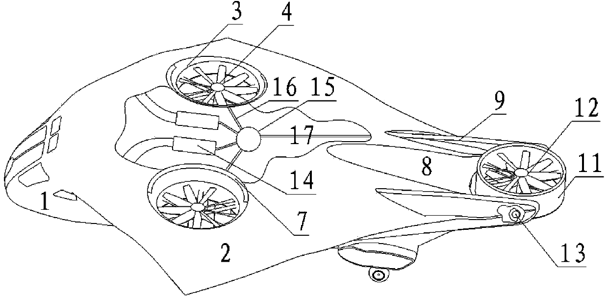
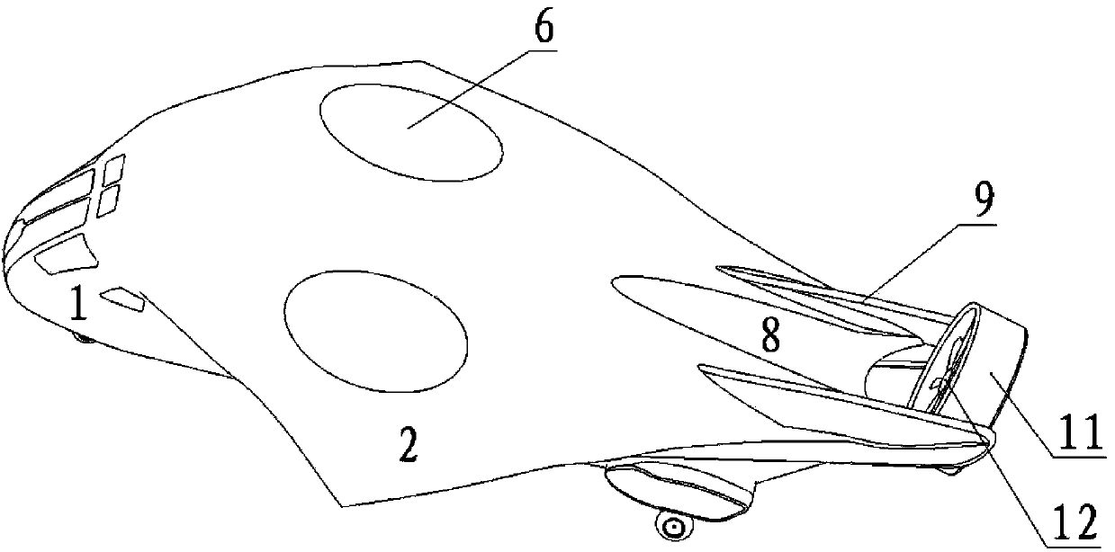
[0015] Such as figure 1 and figure 2 As shown, it includes a fuselage 1 and a wing 2, and a cylindrical through hole 3 with a circular chamfer is opened on the left and right sides of the wing 2 with the fuselage axis as the axis of symmetry to form a duct wall. The middle part of the cylindrical through hole 3 is provided with a rotor 4, the rotor 4 is connected to the speed reducer 15 through the transmission shaft 16, and the duct wall and the rotor 4 together form a lift duct; The upper and lower wall panels of the wing 2 are respectively provided with an inner compartment 7 in the direction of the fuselage axis for a built-in cover 6, and the upper surface or the lower surface of the cover 6 conforms to the upper surface or the lower surface of the wing 2 respectively. And slide out the upper and lower ports of the completely covered thr...


PUM


Abstract

The invention relates to a vertical take-off and landing rotor aircraft with ducts built in wings, relates to the technical field of the vertical take-off and landing rotor aircraft, and particularly relates to the technical field of the vertical take-off and landing rotor aircraft with the ducts built in the wings. The wings are provided with lifting ducts; an inner bin is arranged on the inner wall of each lifting duct close to upper and lower wallboards of the wings so as to built in an duct cover; the duct cover can realize opening and closing of the lifting ducts; a diversion trench is arranged on the tail part of a fuselage; two sides of the diversion trench are provided with two supporting members and connect a tilting thrust duct arranged at the tail part of the fuselage to the fuselage through a tilting control mechanism; the tilting thrust duct is composed of coaxial tilting duct walls and coaxial thrust dual rotors; and engines are arranged in the fuselage and transmit power to the lifting duct and the tilting thrust duct through a reducer respectively. The aircraft increases an adjustable scope of the whole aircraft along an axis direction of the fuselage while not greatly weighting the whole aircraft, prevents bareness of the rotors, and increases propulsive efficiency of the aircraft.

Description

technical field [0001] The invention relates to the technical field of vertical take-off and landing rotorcraft, in particular to the technical field of vertical take-off and landing rotorcraft with built-in ducts in wings. Background technique [0002] The vertical take-off and landing rotorcraft has both vertical take-off and landing capabilities and high-speed forward flight capabilities. It is mainly used in complex take-off and landing environments lacking airport support, and has fast task responsiveness. Tilt rotor aircraft V-22 is currently the only mass-produced aircraft of this type. It is mainly equipped with a propulsion device that can be tilted at the end of the wing. The propulsion device is composed of an engine, a reducer and a rotor. By adjusting the propulsion device The angle between the axis and the axis of the fuselage is used to convert the flight attitude, that is, when taking off and landing vertically, the axis of the propulsion device is perpendicu...

Claims


Application Information

Patent Timeline
Patent Type & Authority Applications(China)
IPC IPC(8): B64C27/20B64C27/52
Inventor 刘衍涛邓景辉周楫
Owner CHINA HELICOPTER RES & DEV INST
Why Eureka
Try Eureka