Cooling device

A technology of cooling device and cooling unit, applied in the direction of power plant, liquid cooling, engine cooling, etc., can solve the problems of increased manufacturing and use costs, large horizontal or vertical volume, small installation space, etc., to save manufacturing and use costs Effect

Inactive Publication Date: 2014-12-03
SUZHOU INDAL PARK ELION TECH
View PDF8 Cites 5 Cited by
  • Summary
  • Abstract
  • Description
  • Claims
  • Application Information

AI Technical Summary

Problems solved by technology

[0004] In the prior art, the water tank and the intercooler in the cooling device are in the same vertical plane, or their central axes are on a straight line. This arrangement, on the one hand, requires a high-power fan to make the cooling device reach the desired level. The purpose of heat dissipation and temperature adjustment of the engine increases the cost of manufacture and use. On the other hand, the power of the electronic fan is often very small, and it is difficult to apply it to the cooling device arranged in this way
At the same time, the above-mentioned cooling device needs to occupy a fixed cubic space in the automobile. With the development of the automobile industry, for example: the overall structure of the automobile is becoming smaller and smaller, and the installation space for the cooling device of the automobile is also getting smaller and smaller; The arrangement structure of the cooling device in the prior art causes its horizontal or vertical volume to be too large, which cannot meet the needs of automobile development

Method used


Image

  • Cooling device
  • Cooling device
  • Cooling device

Examples


Embodiment Construction

[0046] The present invention will be described in detail below in conjunction with specific embodiments shown in the accompanying drawings. However, these embodiments do not limit the present invention, and any structural, method, or functional changes made by those skilled in the art according to these embodiments are included in the protection scope of the present invention.

[0047] For the convenience of description, up, down, front, back, etc. appearing below are reference angles, and they are defined as front and back respectively from left to right along the horizontal direction of the illustration, and respectively defined from top to bottom in the vertical direction of the illustration. Up and down, but objects described by these reference angles should not be limited by these terms, which are used only to distinguish these described objects from one another.

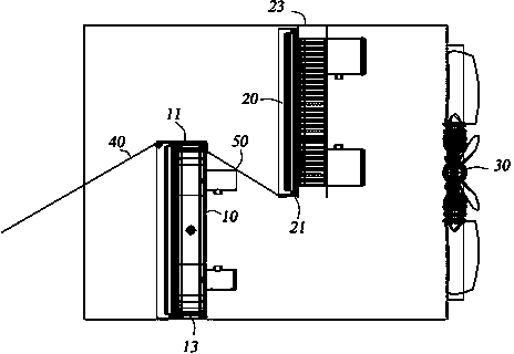
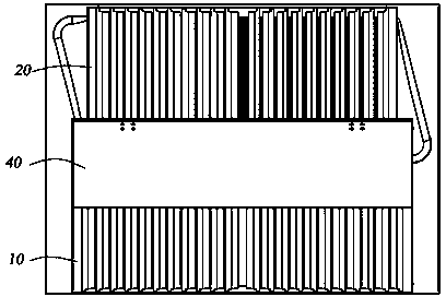
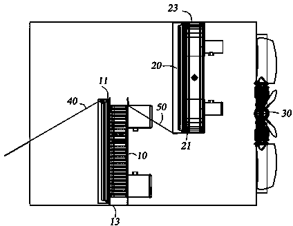
[0048] The cooling device is usually installed in the vehicle body to dissipate heat from the liquid and / or ...


PUM


Abstract

The invention provides a cooling device. The cooling device comprises a first cooling part and a second cooling part which are distributed front and back and a fan component used for driving airflow to inflow from the front side of the first cooling part and outflow from the rear side of the second cooling part, wherein the first cooling part and the second cooling part are arranged at an interval in the horizontal direction; part of the first cooling part and the second cooling part are intersected in the longitudinal direction; a first guiding plate is movably arranged on the side, far away from the second cooling part, of the first cooling part; a second guiding plate is arranged between the first cooling part and the second cooling part. According to the invention, a water tank and an intercooler are redistributed, so that unused space in a vehicle can be more reasonably used; in addition, the guiding plates are arranged in the cooling device, so that proportion of the airflow flowing into a first cooling mechanism and a second cooling mechanism can be accurately controlled, and the manufacturing and utilizing costs are lowered.

Description

technical field [0001] The invention relates to the technical field of automobile manufacturing, in particular to a cooling device. Background technique [0002] The cooling device is the main part of the car, its function is to dissipate heat, including parts such as water tank and intercooler, the water tank is used to cool down the coolant flowing through it, so as to achieve the effect of heat dissipation and temperature regulation of the engine ; The intercooler is used to cool the compressed air flowing through it, thereby improving the ventilation efficiency of the engine. [0003] For the heat dissipation of the car's engine, usually the car's engine and the fan on the cooling device are connected by a belt. When the car is running, the engine is started, and the engine drives the belt, which in turn drives the fan to rotate to realize heat dissipation and temperature regulation of the coolant; this structure Cooling device, because the speed of the fan is determine...

Claims


Application Information

Patent Timeline
Patent Type & Authority Applications(China)
IPC IPC(8): F01P3/18F01P11/10F01P7/04F02B29/04B60K11/04
CPCY02T10/12
Inventor 陈江峰
Owner SUZHOU INDAL PARK ELION TECH
Why Eureka
Try Eureka