Adiabatic-isothermal shift technique for high-concentration CO raw gas

A technology of isothermal transformation and raw gas, applied in the fields of inorganic chemistry, non-metallic elements, chemical instruments and methods, etc., can solve the problems of process flow setting and control method differences, etc., to reduce one-time usage, reduce system resistance, and save The effect of energy consumption

Active Publication Date: 2014-12-10
青岛联信催化材料有限公司
View PDF3 Cites 45 Cited by
  • Summary
  • Abstract
  • Description
  • Claims
  • Application Information

AI Technical Summary

Problems solved by technology

Due to the difference of raw material gas, there are big differences in the setting of process flow and control method

Method used


Image

  • Adiabatic-isothermal shift technique for high-concentration CO raw gas
  • Adiabatic-isothermal shift technique for high-concentration CO raw gas

Examples


Embodiment 1

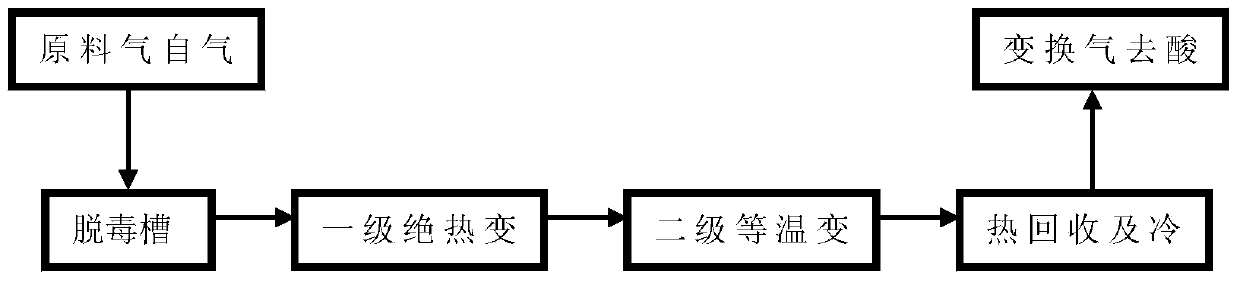
[0036] "Adiabatic + isothermal" two-stage sulfur conversion

[0037] The raw material gas with a CO dry basis volume content of 70% and a water-gas ratio of 1.1 first enters the detoxification tank to remove dust and other impurities, and then exchanges heat with the gas after the first-stage adiabatic shift reaction to 240°C and enters the first reactor Carry out one-stage shift reaction, the hot spot temperature of the first-stage reactor bed layer is 400°C, the reaction pressure is 3.6MPa, and the dry basis content of CO in the outlet gas of the first-stage reactor is 30%; the gas after the first-stage adiabatic shift is firstly mixed with The inlet raw material gas of the first-stage reactor is heat-exchanged, and then passes through the self-produced medium-pressure saturated steam of a steam superheater superheating system, and then recovers heat through the waste pot, adjusts the temperature to 240°C, and enters the second-stage isothermal shift reactor Continue the con...

example 1

[0039] The "adiabatic + isothermal" two-stage sulfur-resistant shift production process described in Example 1, wherein a layered temperature-controlled reactor is used for the first-stage shift reaction, and a cobalt-molybdenum-based sulfur-tolerant shift catalyst is used in the CO shift reaction process, and the qualified The shift gas can be used in synthetic ammonia and hydrogen production units.

Embodiment 2

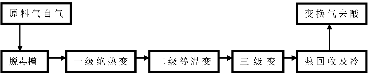
[0041] "Adiabatic + isothermal + adiabatic" three-stage sulfur conversion

[0042] The raw material gas with a CO dry basis content of 70% and a water-gas ratio of 0.76 first enters the detoxification tank to remove impurities such as dust, and then exchanges heat with the gas after the first-stage adiabatic shift reaction to 240°C, and then enters the first reactor for further processing. First-stage shift reaction, the hot spot temperature of the first-stage reactor bed is 350°C, the reaction pressure is 3.6MPa, and the dry content of CO in the gas at the outlet of the first-stage reactor is 40%; The inlet raw material gas of the primary reactor is heat-exchanged, and then passes through the medium-pressure saturated steam produced by the superheating system of a steam superheater, and then superheated steam and quenching water are added, and the temperature is adjusted to 250°C to enter the second-stage isothermal transformation reaction The reactor continues to shift react...


PUM


Abstract

The invention provides a novel CO sulfur-tolerant shift technique which at least comprises a CO sulfur-tolerant shift production procedure composed of an adiabatic shift section and an isothermal shift section. Compared with the traditional adiabatic shift technique, the technique can simplify the shift process, reduce the equipment investment, lower the system resistance and reduce the one-time use amount of the catalyst. Compared with the direct isothermal shift technique, the isothermal reactor is arranged after the adiabatic reactor, the reaction heat generated by the primary adiabatic shift can ensure the inlet temperature of the isothermal shift reactor and avoid the problem of difficulty in self balancing of heat quantity in the direct isothermal shift technique, and thus, the technique can reasonably utilize the energy, avoid the problem of blockage since dust and other impurities in the raw gas enter the isothermal reactor, and ensure the long-period stable operation of the complete device.

Description

technical field [0001] The present invention provides a novel CO sulfur-resistant conversion process for producing ammonia synthesis gas, hydrogen and methanol synthesis gas using coal as a raw material, specifically providing an "adiabatic + isothermal" process suitable for high-pressure and high-CO concentration feed gas conversion A new type of CO sulfur-resistant conversion process. Background technique [0002] As an efficient and clean coal gasification technology, pulverized coal gasification technology using coal as raw material has been widely introduced, developed and applied in my country's coal chemical industry. The CO content in the raw material gas produced by pulverized coal gasification is as high as 60%. For ammonia or hydrogen production units, four stages of adiabatic transformation are installed in the existing mature technology for deep transformation. The entire process is long, the system resistance is large, and by-products The steam grade is relati...

Claims


Application Information

Patent Timeline
Patent Type & Authority Applications(China)
IPC IPC(8): C01B3/12
Inventor 肖杰飞刘博男王利军杜伟东张晋李袖章高辉纵秋云
Owner 青岛联信催化材料有限公司
Why Eureka
Try Eureka