
Damper for gas turbines

A gas turbine and damper technology, applied in combustion chambers, combustion methods, combustion equipment, etc., can solve problems such as hindering dampers, and achieve the effect of extending operating life

Active Publication Date: 2014-12-03
ANSALDO ENERGIA IP UK LTD
View PDF9 Cites 2 Cited by
  • Summary
  • Abstract
  • Description
  • Claims
  • Application Information

AI Technical Summary

Problems solved by technology

In fact, the thermal expansion of the different layers that make up the combustion chamber prevents the direct application of such dampers

Method used


Image

  • Damper for gas turbines
  • Damper for gas turbines

Examples


Embodiment Construction

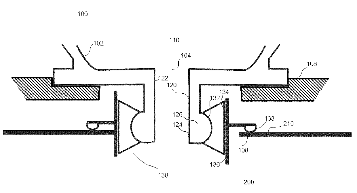
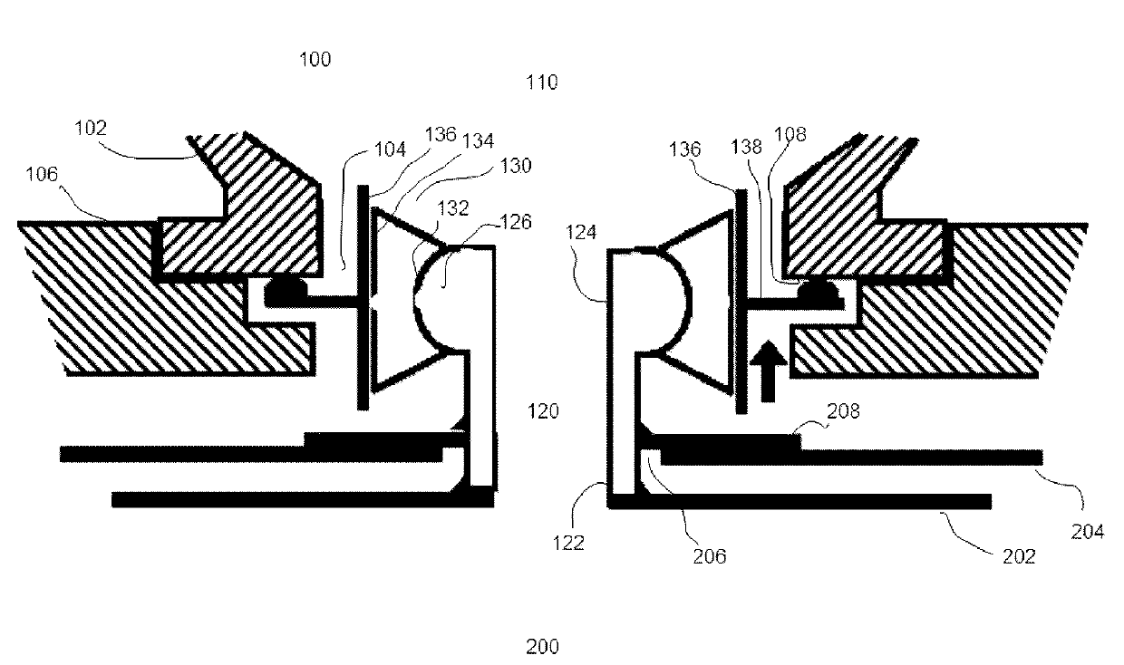
[0045] figure 1 A schematic cross-sectional view of a damper 100 with a portion of a combustor 200 of a gas turbine is shown according to an embodiment of the invention, with some portions cut away for clarity. The damper 100 includes a resonant cavity 110 having a box shape or a cylindrical shape as defined by the peripheral wall 102 and the inlet 104 . Such as figure 1 As shown, the main part of the resonant cavity 110 is cut away, because this will not hinder a complete and complete understanding of the technical solution of the present invention. Also, for clarity and conciseness, figure 1 Only those parts of the combustion chamber 200 that are closely relevant to the invention are shown. Resonant cavity 110 consists of figure 1 Fasteners, not shown, are hermetically attached to the structure 106 of the combustion chamber 200 . In an exemplary embodiment of the invention, the structure 106 of the combustor 200 may be a shell of the combustor 200 . Those skilled in th...


PUM


Abstract

The invention relates to a damper for reducing the pulsations in a combustion chamber of a gas turbine. The damper includes a resonator cavity with an inlet and a neck tube in flow communication with the interior of the combustion chamber and resonator cavity, and a compensation assembly pivotably connected with the neck tube. The compensation assembly is inserted between the resonator cavity and the combustion chamber to permit relative rotation between the combustion chamber and the resonator cavity. With the damper according to the present invention, by way of providing the compensation assembly, it is assured the relative rotation between the combustion chamber and the resonator cavity is compensated, hence operation life is elongated.

Description

technical field [0001] The present invention relates to a gas turbine, and more particularly to a damper for reducing pulsation in a combustion chamber of a gas turbine. Background technique [0002] In conventional gas turbines, acoustic oscillations typically occur in the combustion chamber of the gas turbine due to combustion instabilities and variations during the combustion process. This acoustic oscillation can develop into a very pronounced resonance. Such oscillations, also known as combustion chamber pulsations, can employ amplitudes and associated pressure fluctuations that subject the combustion chamber itself to severe mechanical loading, which can decisively shorten the lifetime of the combustion chamber and, in the worst case, even cause damage to the combustion chamber. [0003] Typically, a type of damper known as a Helmholtz damper is used to damp the pulsations generated in the combustion chamber of a gas turbine. Currently, a major difficulty in using s...

Claims


Application Information

Patent Timeline
Patent Type & Authority Applications(China)
IPC IPC(8): F23R3/00
CPCF23M2900/05002F23R3/002F23R3/16F23R2900/00014F23R2900/00005F23M99/005F23R3/60F23M20/005
Inventor U.本滋N.奈拉伊
Owner ANSALDO ENERGIA IP UK LTD
Learn More