Rotation variable pitch test stand

A technology of a test bench and a rotating platform, applied in the field of driving equipment testing, can solve the problem that the operation mode of the pitch mechanism cannot be truly reflected.

Inactive Publication Date: 2014-12-03
SIEMENS FACTORY AUTOMATION ENG
View PDF9 Cites 4 Cited by
  • Summary
  • Abstract
  • Description
  • Claims
  • Application Information

AI Technical Summary

Problems solved by technology

[0003] but, figure 1 The test platform shown in can only simulate the pitch state of a single blade, and more importantly, the fixed installation method of the test platform cannot truly reflect the operation mode of the pitch mechanism

Method used


Image

  • Rotation variable pitch test stand
  • Rotation variable pitch test stand
  • Rotation variable pitch test stand

Examples


Embodiment Construction

[0020] In order to make the objectives, technical solutions and advantages of the present invention clearer, the following examples are used to further describe the present invention in detail.

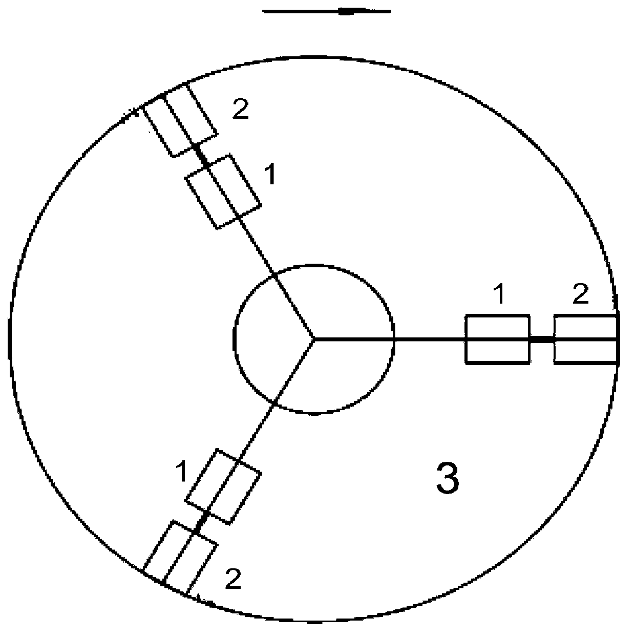
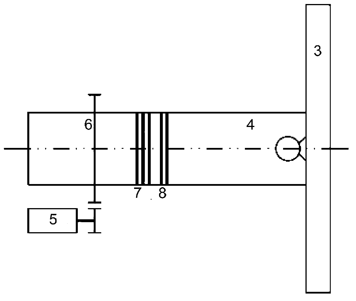
[0021] Since the actual wind power blade is disturbed by the wind speed during the rotation process, the blade load changes and then affects the motor pitch system, so a core idea of ​​the present invention is to introduce a rotating mechanism in the pitch test platform, thereby Realistically simulate the actual operation of the pitch mechanism.

[0022] In the pitch test bench of the specific embodiment of the present invention, such as figure 2 As shown, including the pitch motor 1 and the load motor 2 in the original test bench, in addition, the pitch test bench also includes a rotating mechanism, the rotating mechanism includes a rotatable rotating platform 3, the pitch motor 1 and the load motor 2 are arranged on one side of the rotating platform 3 . The connection between the...


PUM


Abstract

The invention discloses a rotation variable pitch test stand comprising a variable pitch motor, a load motor and a rotation mechanism. The rotation mechanism comprises a rotatable rotation platform. The variable pitch motor and the load motor are arranged on the rotation platform. According to the rotation variable pitch test stand, the variable pitch motor and the load motor are arranged on the rotatable rotation platform, a motor power supply problem is solved by adopting a slip ring electrification mode, the state of influence of pitch blade load change on a motor variable pitch system in wind speed disturbance is simulated, and the real operation mode of a variable pitch mechanism is reflected.

Description

technical field [0001] The invention relates to a test technology for driving equipment, in particular to a rotary pitch test stand. Background technique [0002] When testing the wind turbine pitch motor, in order to simulate the influence of the blade load change on the motor pitch system when the wind speed is disturbed, a test platform for simulating the pitch can be established. The test platform usually includes two parts: the pitch motor drive system 10 and the load motor drive system 20. The entire test platform adopts a fixed installation method, such as figure 1 shown. [0003] but, figure 1 The test platform shown in can only simulate the pitch state of a single blade, and more importantly, the fixed installation method of the test platform cannot truly reflect the operation mode of the pitch mechanism. SUMMARY OF THE INVENTION [0004] In view of this, the purpose of the present invention is to propose a new pitch test bench to simulate the influence state o...

Claims


Application Information

Patent Timeline
Patent Type & Authority Applications(China)
IPC IPC(8): G01R31/34
Inventor 马焉
Owner SIEMENS FACTORY AUTOMATION ENG
Why Eureka
Try Eureka