Optical fiber connector and optical fiber connector assembly using optical fiber connector

A technology for optical fiber connectors and components, which is applied in the coupling of optical waveguides, etc., can solve the problems of poor tensile strength of optical fiber connectors, detachment of pins, affecting the connection effect of optical fiber connectors, etc., so as to ensure the quality of signal transmission, The effect of reducing radial size and improving tensile strength

Inactive Publication Date: 2014-12-03
CHINA AVIATION OPTICAL-ELECTRICAL TECH CO LTD
View PDF4 Cites 10 Cited by
  • Summary
  • Abstract
  • Description
  • Claims
  • Application Information

AI Technical Summary

Problems solved by technology

[0002] Existing optical fiber connectors such as "A Tensile Active Optical Fiber Connector and Its Components" disclosed in Chinese patent CN202710790U, the optical fiber connector includes a connector housing with a plug-in end at the front end, and an outer peripheral rotating sleeve of the connector housing There is a connecting nut, the inner peripheral surface of the connecting nut is provided with an internal thread for screwing and fitting with the external thread on the housing of the adapter connector, and a pin part that can move back and forth is installed in the housing of the connecting body. The needle part includes a pin holder and a pin fixed on the pin holder. The front end of the connector housing is provided with a limit step for blocking and matching with the pin holder to limit the forward movement limit of the pin part. , the connector housing is provided with a baffle plate at the rear end of the pin holding body, and a pre-tension spring is installed on the top between the baffle plate and the pin holding body, and the pin parts can have a certain The range of axial floating, so that although the elastic contact between the pin and the mating connector is achieved, the service life of the pin is guaranteed, but the tensile capacity of the optical fiber connector is not strong, and the pin is easy to be damaged in actual use. The pulling force of the optical cable moves backward and disengages from the pin part of the adapter connector, which affects the connection effect of the optical fiber connector. Therefore, this type of optical fiber connector is not suitable for use in some environments with high working tension.

Method used


Image

  • Optical fiber connector and optical fiber connector assembly using optical fiber connector
  • Optical fiber connector and optical fiber connector assembly using optical fiber connector
  • Optical fiber connector and optical fiber connector assembly using optical fiber connector

Examples


Embodiment Construction

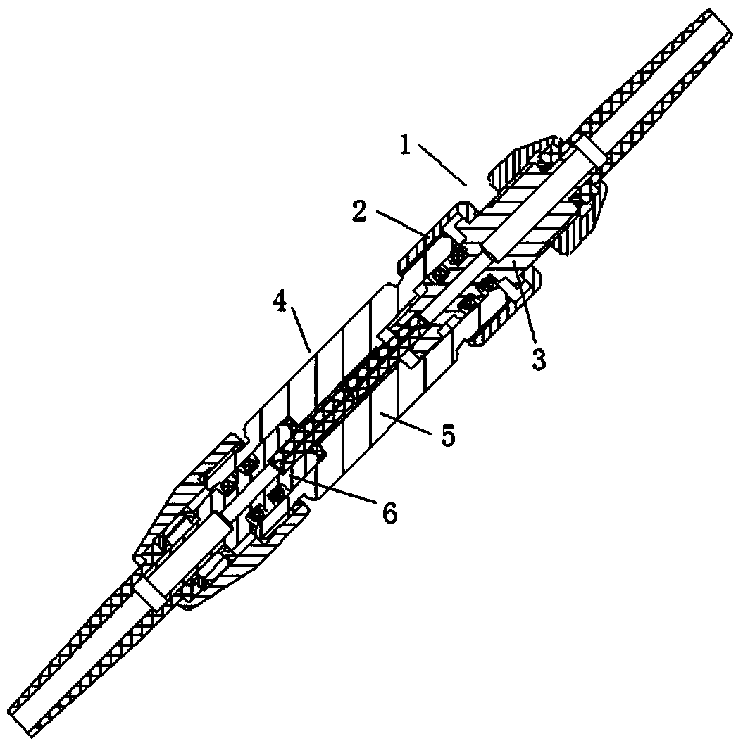
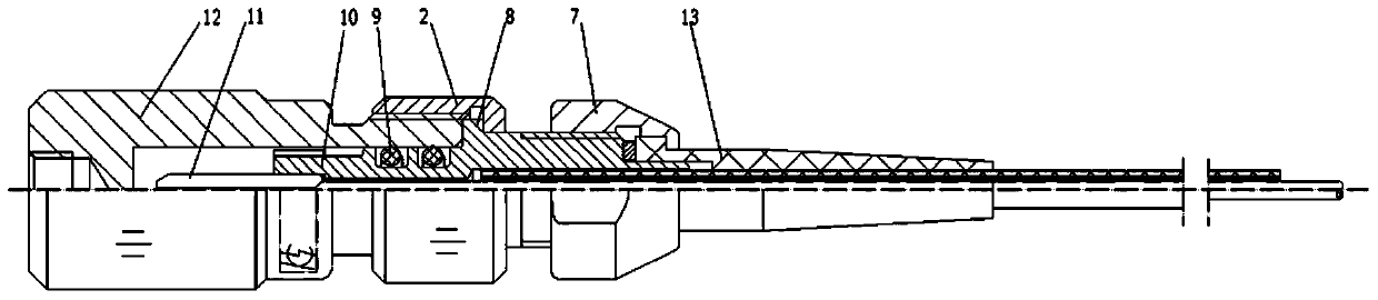
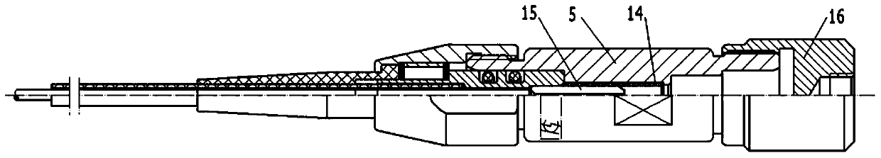
[0016] Examples of fiber optic connector assemblies are Figure 1~3 Shown: includes a plug 1 and a socket 4, the socket includes a socket housing 5 and a socket pin part 6 fixedly installed in the socket housing, and the outer peripheral surface of the plug-in end of the socket housing is provided with housing external threads. The plug includes a plug pin part 3 whose front end is a plug-in end. The plug pin part includes a pin holder 10 on which a plug pin 11 is installed. The connecting nut 2 is rigidly docked with the socket pin 15 of the socket pin part, and the inner side of the connecting nut is sheathed on the pin holding body with a sealing ring 9 for sealingly cooperating with the plug-in end of the socket housing. The pin holding body is provided with a body external thread on the rear outer peripheral surface of the connecting nut, and the body external thread is screwed with a fastening nut 7 for fixing the corresponding tail sheath 13 to the rear end of the pin h...


PUM


Abstract

The invention relates to an optical fiber connector and an optical fiber connector assembly using the optical fiber connector. The optical fiber connector comprises a pin component, the front end of which is an insertion end. The pin component comprises a pin holder provided with a pin. The pin holder is rotatably sleeved with a connection nut in screw cooperation with an external thread at the insertion end of a housing of a corresponding adapter connector so as to enable the pin to be in rigid butting with an adapter pin of the adapter connector. The pin holder is provided with an anti-dropping structure for being in limitation cooperation with the connection nut to stop the connection nut to get out of the pin holder along the axial direction. The invention provides an optical fiber connector which is strong in tension resistance capability.

Description

technical field [0001] The invention relates to the field of connectors, in particular to an optical fiber connector and an optical fiber connector assembly using the optical fiber connector. Background technique [0002] Existing optical fiber connectors such as "A Tensile Active Optical Fiber Connector and Its Components" disclosed in Chinese patent CN202710790U, the optical fiber connector includes a connector housing with a plug-in end at the front end, and an outer peripheral rotating sleeve of the connector housing There is a connecting nut, the inner peripheral surface of the connecting nut is provided with an internal thread for screwing and fitting with the external thread on the housing of the adapter connector, and a pin part that can move back and forth is installed in the housing of the connecting body. The needle part includes a pin holder and a pin fixed on the pin holder. The front end of the connector housing is provided with a limit step for blocking and ma...

Claims


Application Information

Patent Timeline
Patent Type & Authority Applications(China)
IPC IPC(8): G02B6/38
Inventor 胡治国
Owner CHINA AVIATION OPTICAL-ELECTRICAL TECH CO LTD
Why Eureka
Try Eureka