
Sample platform and microscope system

A sample stage and sample tank technology, which is applied in sample introduction/extraction, parts of particle separator tubes, etc., can solve the problems of reducing the efficiency of sample analysis and testing and complex operation.

Active Publication Date: 2014-12-03
胜科纳米(苏州)股份有限公司
View PDF7 Cites 8 Cited by
  • Summary
  • Abstract
  • Description
  • Claims
  • Application Information

AI Technical Summary

Problems solved by technology

[0005] The object of the present invention is to provide a kind of sample stage and microscope system, to solve the problem in the working mode of electron backscatter diffraction and transmission electron diffraction in the prior art because there is no sample stage suitable for the working mode of transmission electron diffraction. In the process of switching between working modes, the operation is complicated, which reduces the efficiency of sample analysis and testing

Method used


Image

  • Sample platform and microscope system
  • Sample platform and microscope system
  • Sample platform and microscope system

Examples


Embodiment Construction

[0024] The sample stage proposed by the present invention will be further described in detail below in conjunction with the accompanying drawings and specific embodiments. Advantages and features of the present invention will be apparent from the following description and claims. It should be noted that all the drawings are in a very simplified form and use imprecise scales, and are only used to facilitate and clearly assist the purpose of illustrating the embodiments of the present invention.

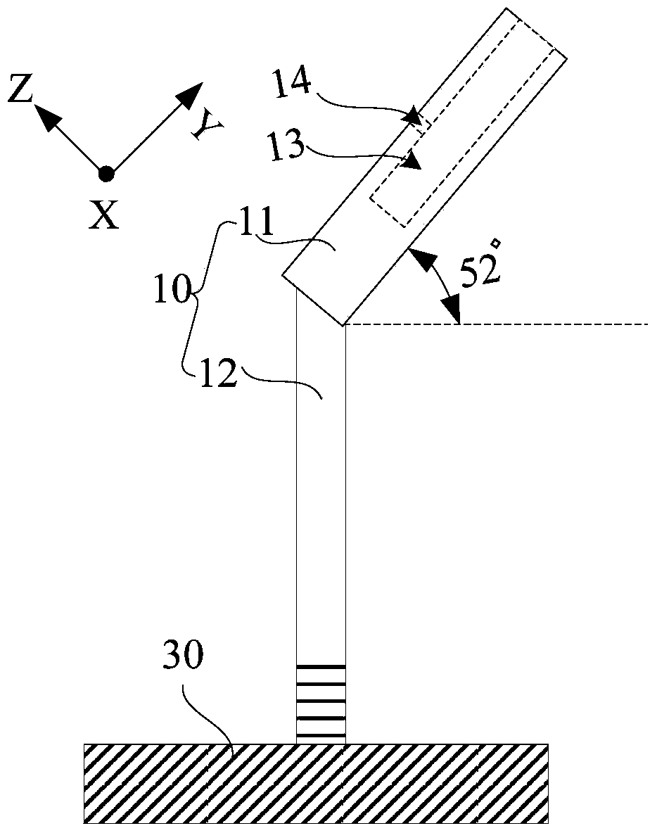
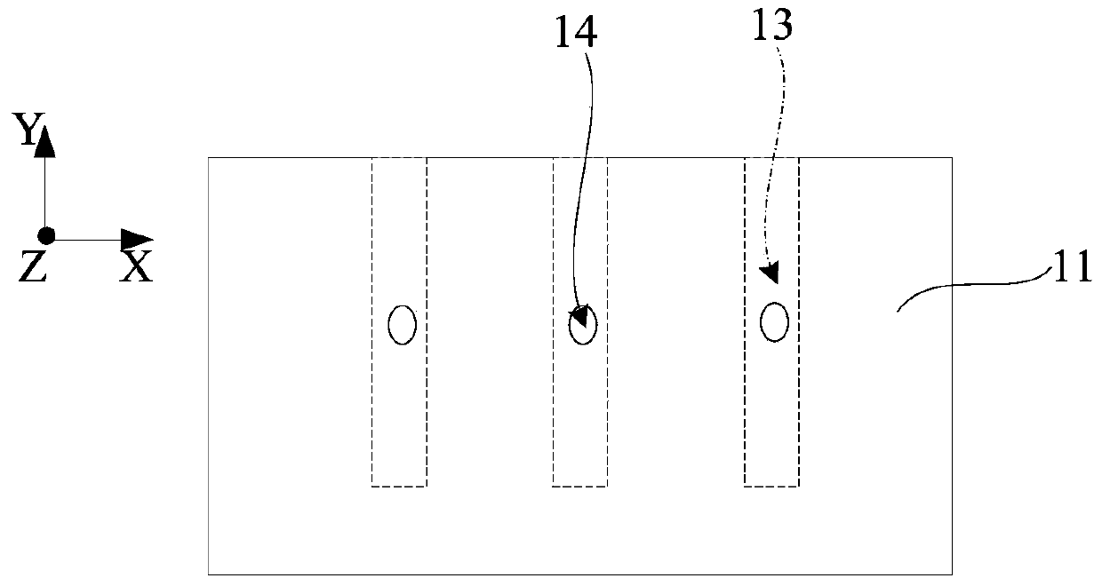
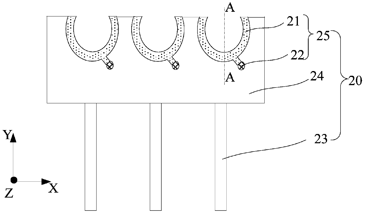
[0025] Please refer to figure 1 and image 3 ,in, figure 1 It is a side view of the support frame fixed on the stage in an embodiment of the present invention, figure 1 It is a top view of the sample tank in an embodiment of the present invention. combine figure 1 and figure 2 , the sample stage suitable for the working mode of the electron backscatter diffraction type and the working mode of the transmission electron diffraction includes: a support frame 10, and a sample groove...


PUM


Abstract

The invention provides a sample platform and a microscope system. The sample platform is applicable to an electronic back-scattering diffraction-type work mode and a transmission electronic diffraction work mode. The sample platform includes a support frame, and a sample sink assembled on the support frame. The support frame includes a jack stand and a support rod. The support rod is connected with the jack stand. The jack stand forms an angle of 142 degrees with the support rod. When the sample platform is used, the sample platform is fixed on an object table of a secondary electronic microscope and the support rod is made form an angle of 90 degrees with the object table. Through a structure in which the angle between the jack stand and the support rod is designed to be 142 degrees and the angle between the support rod and the object table to be 90 degrees, when a sample is loaded on the sample platform for test analysis, through adjustment of tilting and / or rotation of the object table, a tilt angle between the sample and the horizontal plane can be adjusted in a large range so that switching between the electronic back-scattering diffraction-type work mode and the transmission electronic diffraction work mode can be carried out according to practical demands.

Description

technical field [0001] The invention relates to the technical field of sample stage manufacture, in particular to a sample stage and a microscope system. Background technique [0002] Electron backscattered diffraction technique is a testing technique based on secondary electron microscopy for grain size distribution and orientation distribution on the material surface. Usually, in the process of electron backscatter diffraction, the sample for electron backscatter diffraction needs to form an angle of 70 degrees with the horizontal plane, and electrons enter the sample at a grazing angle, so under this condition, the lateral resolution is greater than 100 nanometers, which is very Difficult to analyze grains smaller than 100 nm. Therefore, improving the lateral resolution of electron backscattered diffraction technology is a hot research direction now. [0003] Generally, the method adopted by those skilled in the art in order to improve the lateral resolution of electron...

Claims


Application Information

Patent Timeline
IPC IPC(8): H01J49/04
Inventor 沈轶强
Owner 胜科纳米(苏州)股份有限公司
Learn More