
Diagnostic test kits employing an internal calibration system

a technology of internal calibration and diagnostic test kits, which is applied in the direction of instruments, biological material analysis, measurement devices, etc., can solve the problems of burdensome pre-mixing of assay reagents, inability to readily incorporate internal calibration techniques into lateral flow devices, and over-complicated requirements

Active Publication Date: 2006-10-05
KIMBERLY-CLARK WORLDWIDE INC
View PDF35 Cites 31 Cited by
  • Summary
  • Abstract
  • Description
  • Claims
  • Application Information

AI Technical Summary

Benefits of technology

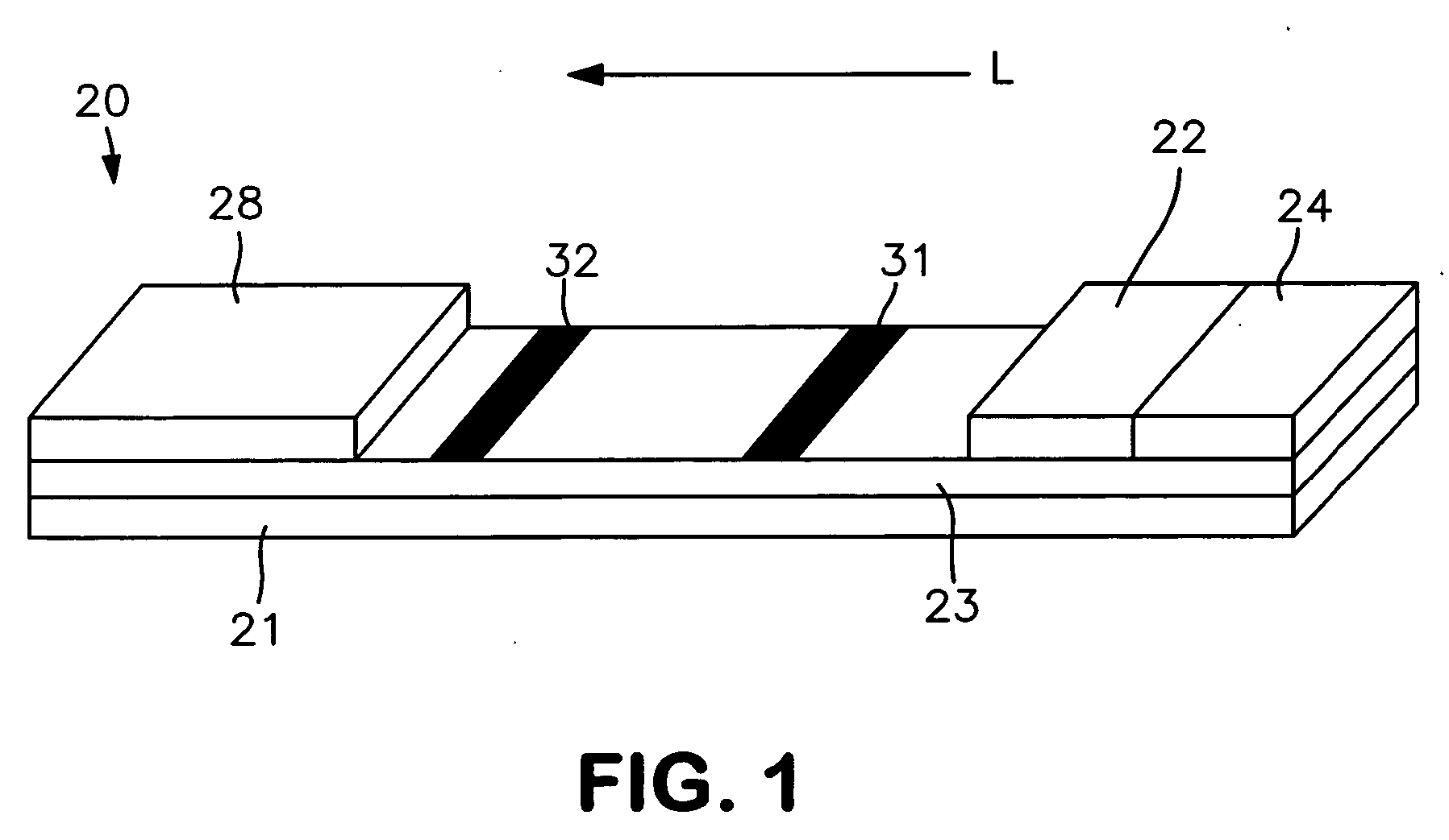
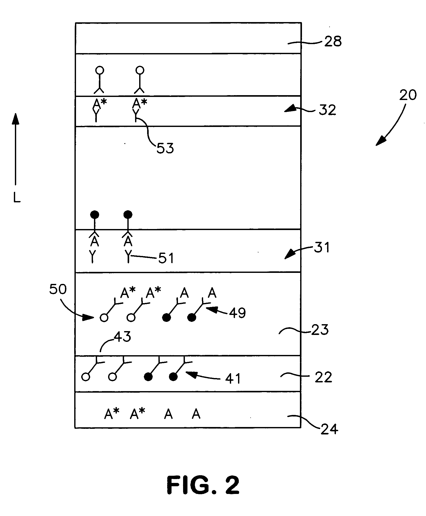
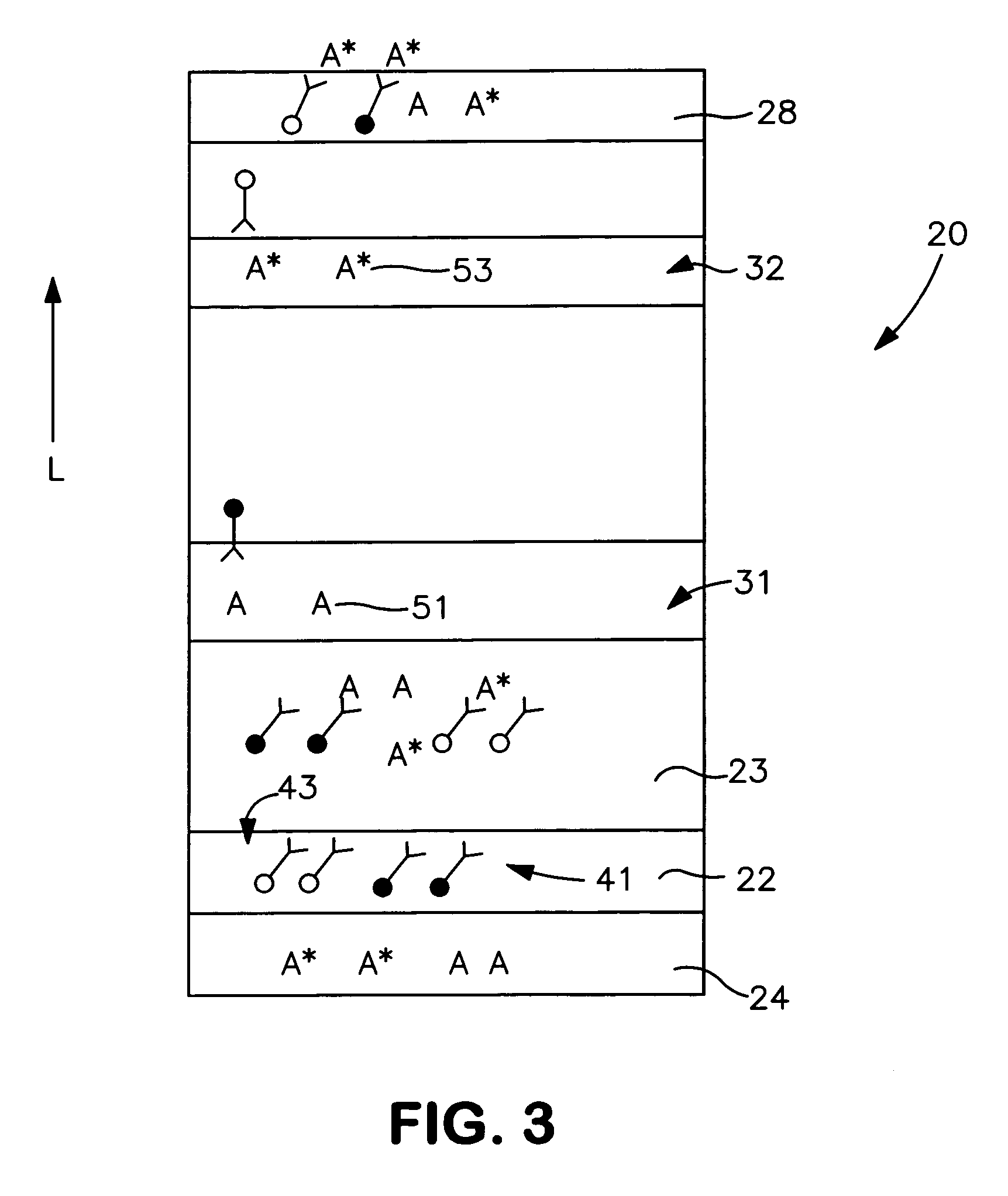
[0006] In accordance with one embodiment of the present invention, a diagnostic test kit is disclosed for detecting the presence or quantity of a test analyte within a test sample. The diagnostic test kit comprises a lateral flow assay device comprising a porous membrane. The porous membrane defines a detection zone and a calibration zone. A first receptive material is immobilized within the detection zone and a second receptive material is immobilized within the calibration zone. Besides the lateral flow assay device, the diagnostic test kit also comprises a plurality of assay reagents, one or more of which are disposed on the lateral flow assay device. The assay reagents comprise a calibration analyte, detection probes, and calibration probes. The detection probes are conjugated with a first specific binding member configured to preferentially bind to the test analyte, the first receptive material, or combinations thereof. The calibration probes are conjugated with a second specific binding member configured to preferentially bind to the calibration analyte, the second receptive material, or combinations thereof.

Problems solved by technology

However, it is often subject to interference from environmental and batch-to-batch variations, and is thus unreliable.
Unfortunately, such internal calibration techniques are not readily incorporated into lateral flow devices, which involve heterogeneous separation of the analyte using chromatographic methods.
In addition, the requirement for pre-mixing the assay reagents is burdensome and overly complicated, particularly for point-of-care applications in which the ultimate user is not a trained medical professional or technician.

Method used


Image

  • Diagnostic test kits employing an internal calibration system
  • Diagnostic test kits employing an internal calibration system
  • Diagnostic test kits employing an internal calibration system

Examples


example 1

[0056] The ability to form a lateral flow assay device in accordance with the present invention was demonstrated. A nitrocellulose porous membrane (HF 120 from Millipore, Inc.) having a length of approximately 30 centimeters was laminated onto supporting cards. Monoclonal antibody for C-reactive protein was immobilized on the porous membrane to form a detection zone. The antibody was obtained from BiosPacific, Inc. (Catalog #A58040136P) and had a concentration of 1 milligram per milliliter. Monoclonal antibody for β-HCG (1 milligram per milliliter) was also immobilized on the porous membrane to form a calibration zone. A cellulose wicking pad (Millipore Co.) was laminated with one end (closer to the calibration zone) of the membrane. The membrane samples were then dried for 1 hour at a temperature of 37° C.

[0057] A particle suspension was formed by mixing 36 microliters of gold particles conjugated with anti-CRP monoclonal antibody (BiosPacific, Inc., Catalog #A58110228P), 100 micr...

example 2

[0058] The ability to detect CRP in accordance with the present invention was demonstrated. Five lateral flow devices (Samples 1-5) were made as described in Example 1. A mixing solution containing 60 microliters of CRP (90 nanograms per milliliter) and 60 microliters of β-hCG (50 nanograms per milliliter) was applied to the sample pad of each of five lateral flow devices. After 30 minutes of development at room temperature, the color density of the detection zone and calibration zone was measured using a reflectance spectrophotometer. The color intensity for each zone is listed below in Table 1.

TABLE 1Color Intensity DataDetection ZoneDetection ZoneSampleIntensity (Id)Intensity (Ic)Id / Ic188.28595.2790.92659293.55498.3220.95115391.85098.8730.92897494.286101.5440.92852592.58099.9900.92589

[0059] The mean, standard deviation, and % CV (coefficient of variance, or ratio of standard deviation to mean) for Id was 92.111, 2.33127, and 2.531, respectively. On the other hand, the mean, sta...

example 3

[0060] The ability to detect CRP in accordance with the present invention was demonstrated. Fifteen lateral flow devices (Samples 1-15) were made as described in Example 1 and divided into three groups. The first group was stored at room temperature, the second group was heated at 65° C. for 40 minutes, and the third group was heated at 65° C. for 210 minutes. A mixing solution containing 60 microliters of CRP (100 nanograms per milliliter) and 60 microliters of β-hCG (50 nanograms per milliliter) in tris buffer with 1% Tween® 20 (ICI Americas) was applied to the sample pad of each of fifteen lateral flow devices. After 30 minutes of development at room temperature, the color density of the detection zone and calibration zone was measured using a reflectance spectrophotometer. The color intensities for each group are listed below in Tables 2-4.

TABLE 2Color Intensity Data for First GroupDetection ZoneDetection ZoneSampleIntensity (Id)Intensity (Ic)Id / Ic194.30399.1060.95154293.98097...


PUM

PropertyMeasurementUnit
diameteraaaaaaaaaa
diameteraaaaaaaaaa
lengthaaaaaaaaaa

Abstract

A diagnostic test kit that employs a lateral flow assay device and a plurality of assay reagents for detecting a test analyte within a test sample is disclosed. The assay reagents include detection probes that are capable of producing a detection signal representing the presence or quantity of the test analyte in the test sample. To further enhance detection accuracy, calibration probes are also used that are capable of producing a calibration signal representing the presence or quantity of a calibration analyte. The calibration signal may be utilized to calibrate the detection signal.

Description

BACKGROUND OF THE INVENTION [0001] Various analytical procedures and devices are commonly employed in assays to determine the presence and / or concentration of analytes that may be present in a test sample. For instance, immunoassays utilize mechanisms of the immune systems, wherein antibodies are produced in response to the presence of antigens that are pathogenic or foreign to the organisms. These antibodies and antigens, i.e., immunoreactants, are capable of binding with one another, thereby causing a highly specific reaction mechanism that may be used to determine the presence or concentration of that particular antigen in a biological sample. [0002] There are several well-known immunoassay methods that use immunoreactants labeled with a detectable component so that the analyte may be detected analytically. For example, “sandwich-type” assay formats typically involve mixing the test sample with detection probes conjugated with a specific binding member (e.g., antibody) for the an...

Claims


Application Information

Patent Timeline
Patent Type & Authority Applications(United States)
IPC IPC(8): G01N33/558
CPCG01N33/558Y10T436/105831Y10T436/10G01N33/543G01N33/54388
Inventor SONG, XUEDONGCHIDEBELU-EZE, CHIBUEZE OBIKAYLOR, ROSANN MARIE MATTHEWS
Owner KIMBERLY-CLARK WORLDWIDE INC
Learn More