
A topology of hvdc current limiter

A current limiter and topology technology, which is applied in the field of HVDC DC current limiter topology, can solve the problems of prolonging the time of flow through the shut-off valve, affecting the turn-off angle of the inverter, and affecting the commutation phase, so as to achieve sufficient fast action and fast limit. The speed and amplitude of the current rise, and the effect of shortening the time for the current to become zero

Active Publication Date: 2018-03-30
NORTH CHINA ELECTRIC POWER UNIV (BAODING) +3
View PDF5 Cites 1 Cited by
  • Summary
  • Abstract
  • Description
  • Claims
  • Application Information

AI Technical Summary

Problems solved by technology

[0003] Factors affecting commutation failure include: DC current I dL , Echizen firing angle β, commutation bus voltage U L , Converter transformer transformation ratio k and commutation reactance X C etc., the above factors will affect the turn-off angle of the inverter, thereby affecting the commutation
For example, when a certain fault occurs in the system or the transmission power increases and the DC current I dL When it increases, the current flowing through the converter valve will increase, which will prolong the time for the current flowing through the shut-off valve to become zero, so that the commutation angle μ increases, the shut-off angle γ decreases, and the system is prone to commutation. phase failure

Method used


Image

  • A topology of hvdc current limiter
  • A topology of hvdc current limiter
  • A topology of hvdc current limiter

Examples


Embodiment Construction

[0028] The specific embodiments of the present invention will be further described in detail below in conjunction with the accompanying drawings.

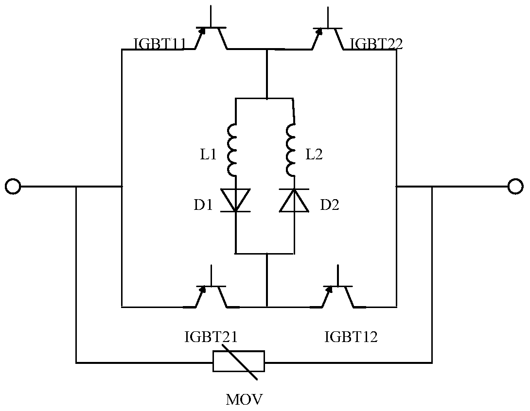
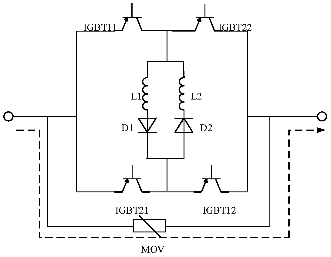
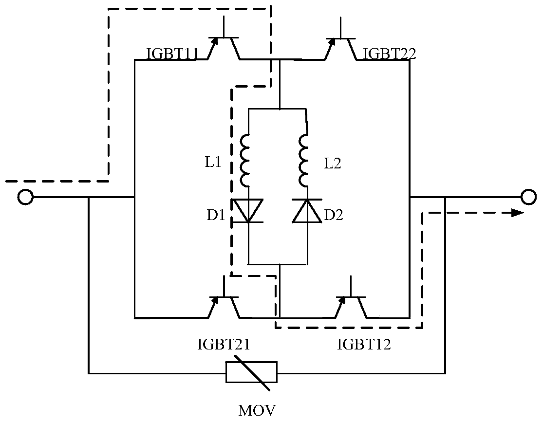
[0029] The invention provides a DC current limiter topology capable of limiting DC current and reducing commutation failure probability of traditional DC transmission. The DC current limiter includes: a parallel IGBT string, and an antiparallel reactor diode group is connected in the middle of the IGBT string to form a bridge structure; the bridge structure is connected in parallel with a bypass switch.

[0030] The number of IGBT strings is 2N, and N is a positive integer. The midpoints of the two IGBT strings are connected by the reactor diode group to form the bridge structure, that is, the Nth IGBT and the N+1th IGBT of the first IGBT string of the IGBT string and the second IGBT string The reactor diode group is connected between the N th IGBT and the N+1 th IGBT to form the bridge structure, and N is a positive integer.

[...


PUM


Abstract

The invention provides an HVDC DC limiter topology. The DC limiter includes IGBT strings connected in parallel. The middles of the IGBI strings are connected with reactor and diode sets connected in parallel in the reverse direction to form bridge type structures. The bridge type structures are connected with a by-pass switch in parallel. The DC limiter is installed at an inverter station DC outlet; the DC limiter is in a bypassing state when a system normally works, and the DC limiter is put into operation when the system fails. Through continuous switching between two current flow paths according to a certain frequency, the DC rise is limited, the time that the current flowing through a shut-off valve becomes zero can be effectively shortened, and the probability of commutation failures for traditional DC transmission is lowered.

Description

technical field [0001] The invention relates to a device in the technical field of power transmission and distribution, in particular to a topology of an HVDC current limiter. Background technique [0002] Due to its unique technical and economic advantages, HVDC transmission has been widely used in long-distance and large-capacity power transmission. However, the existing high-voltage direct current transmission uses thyristors without self-shutoff capability as commutation components, and requires a certain strength of the alternating current system to achieve commutation. Commutation failed. [0003] Factors affecting commutation failure include: DC current I dL , Echizen firing angle β, commutation bus voltage U L , Converter transformer transformation ratio k and commutation reactance X C etc., the above factors will affect the turn-off angle of the inverter, thereby affecting the commutation. For example, when a certain fault occurs in the system or the transmissi...

Claims


Application Information

Patent Timeline
Patent Type & Authority Patents(China)
IPC IPC(8): H02H9/02
Inventor 郭春义李春华刘羽超赵成勇张磊许韦华阳岳希张庆国井雨刚
Owner NORTH CHINA ELECTRIC POWER UNIV (BAODING)
Learn More