Worktable assembly of DLP (Digital Light Processing) photo-curing 3D printer

A 3D printer and workbench technology, applied in the field of workbench components of DLP light-cured 3D printers, can solve the problems of easy damage to the printer frame, affecting the service life of the 3D printer, and affecting the forming effect of objects, so as to improve economic benefits and improve printing quality. The effect of surface finish on objects

Active Publication Date: 2014-12-10
NINGBO YINZHOU INTELLIGENT MFG DIGITAL TECH
View PDF2 Cites 30 Cited by
  • Summary
  • Abstract
  • Description
  • Claims
  • Application Information

AI Technical Summary

Problems solved by technology

Considering that in the current DLP light-curing 3D printer structure, when the printing layer and the bottom surface of the resin tank are demolded, the workbench fixing the resin tank cannot be tilted and offset, and the resin tank is rigid as a whole (the material is generally glass or acrylic), the bottom surface of the groove cannot produce a certain amount of deformation, and the printing platform needs to exert a large external force when it is lifted up against its own weight and gas and hydraulic pressure, which increases the requirements for the overall structural strength of the printer frame, and the printer frame is easily damaged. ; At the same time, the printing layer is rigidly separated from the bottom surface of the resin tank, which will also affect the demoulding effect of the printing layer. Since the photolithography 3D printer constructs the object by printing layer by layer, each printing in the whole construction process of the object Each layer needs to be demolded from the bottom of the resin tank once, so the above structure will seriously affect the final molding effect of the object, cannot improve its surface finish, and will also affect the overall service life of the 3D printer

Method used


Image

  • Worktable assembly of DLP (Digital Light Processing) photo-curing 3D printer
  • Worktable assembly of DLP (Digital Light Processing) photo-curing 3D printer
  • Worktable assembly of DLP (Digital Light Processing) photo-curing 3D printer

Examples


Embodiment 1

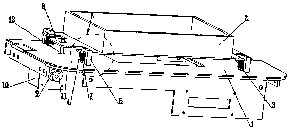
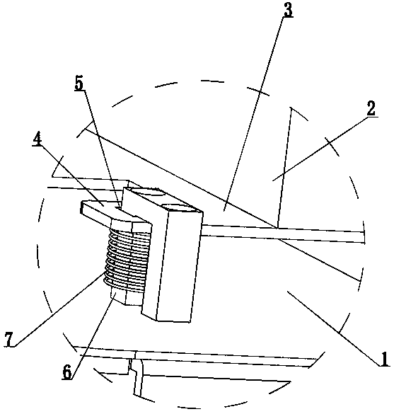
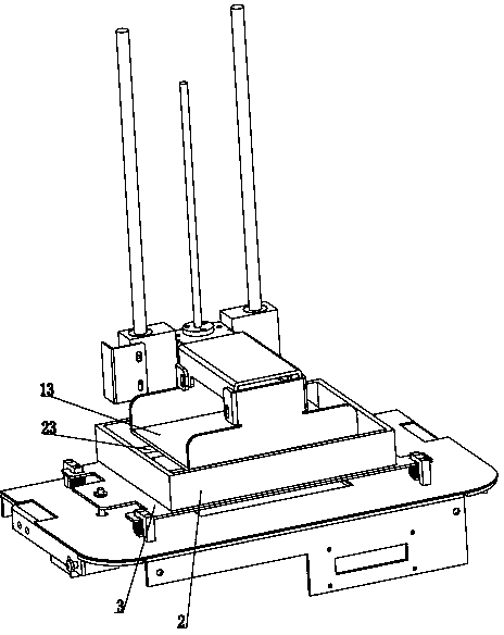
[0032] Such as figure 1 with figure 2 As shown, a workbench assembly of a DLP light-curing 3D printer provided in this embodiment includes a workbench 1 and a transparent resin tank 2, and an installation bottom frame 3 is provided above the workbench 1, and the installation The bottom frame 3 is rectangular and has second flanges 4 at its four corners. Each of the second flanges 4 is provided with a first through hole 5, and U-shaped connectors are connected in series. 6. Both ends of the U-shaped connector 6 are fixed to the base surface of the table 1, and a coil spring 7 is sleeved on the U-shaped connector 6, and the coil spring 7 is located between the second flange 4 and the base of the table 1. Between the two surfaces, a first flange 8 is also provided on one side edge of the above-mentioned installation bottom frame 3, and two flanges 8 are provided below the workbench 1 when receiving the printing layer 24 and the bottom surface 23 of the transparent resin tank 2....

Embodiment 2

[0035] Such as Figure 4 As shown, a workbench assembly of a DLP light-curing 3D printer provided in this embodiment includes a workbench 1 and a transparent resin tank 2, and an installation bottom frame 3 is provided above the workbench 1, and the installation The bottom frame 3 is rectangular and has second flanges 4 at its four corners. Each of the second flanges 4 is provided with a first through hole 5, and U-shaped connectors are connected in series. 6. Both ends of the U-shaped connector 6 are fixed to the base surface of the table 1, and a coil spring 7 is sleeved on the U-shaped connector 6, and the coil spring 7 is located between the second flange 4 and the base of the table 1. Between the two surfaces, a first flange 8 is also provided on one side edge of the above-mentioned installation bottom frame 3, and the servo motor 10 is above the first flange 8, and the output shaft 9 of the servo motor 10 is connected with Eccentric roller 14. When the printing layer 2...

Embodiment 3

[0037] The workbench assembly of a kind of DLP photocuring 3D printer provided in this embodiment, its general structure is consistent with embodiment 1, as Figure 5 As shown, the specific structure in which the bottom frame 3 is connected to the base surface of the workbench 1 through elastic components in the embodiment is as follows: the bottom frame 3 is rectangular, and second flanges 4 are provided at its four corners. , each of the second flanges 4 is fixed with an elastic rubber 15 , and the other end of each elastic rubber 15 is directly fixed to the base surface of the workbench 1 .


PUM

PropertyMeasurementUnit
thicknessaaaaaaaaaa
thicknessaaaaaaaaaa

Abstract

The invention discloses a part of a DLP (Digital Light Processing) photo-curing 3D printer and in particular relates to a worktable assembly of a DLP photo-curing 3D printer. The worktable assembly comprises a worktable and a transparent resin tank, wherein a mounting bottom frame is connected onto the worktable in parallel, the transparent resin tank is fixed on the mounting bottom frame, one side of the mounting bottom frame instantly inclines upwards when a printing layer and the bottom surface of the transparent resin tank are demoulded and the mounting bottom frame can automatically restore after the demoulding process is finished. The worktable assembly achieves the technical effect that the mounting bottom frame can incline and deviate relative to a base plate of the worktable when the DLP photocuring 3D printer works and the printing layer and the bottom surface of the transparent resin tank are demoulded, thereby saving energy and materials and improving the product printing quality of the DLP photocuring 3D printer.

Description

technical field [0001] The invention relates to a component of a DLP light-curing 3D printer, in particular to a workbench assembly of a DLP light-curing 3D printer. Background technique [0002] The working principle of DLP light-curing 3D printers: using digital light processing (DLP) technology, a projector is used to cure liquid photosensitive resin layer by layer. It is capable of printing objects with very fine resolution, surpassing typical fused filament fabrication (FFF) 3D printers. [0003] DLP light curing 3D printer mainly consists of two parts: software and hardware. The above hardware part mainly includes the printer frame, projector, printing platform, workbench and resin tank. In the specific work, the resin tank is fixed on the workbench, and the two together constitute the workbench components of the DLP light-curing 3D printer, the printing platform The continuous layer structure sinks into the resin tank. The resin tank is basically a cylinder filled w...

Claims


Application Information

Patent Timeline
Patent Type & Authority Applications(China)
IPC IPC(8): B29C67/02
Inventor 潘俊深沈杰朱可乐
Owner NINGBO YINZHOU INTELLIGENT MFG DIGITAL TECH
Why Eureka
Try Eureka