Heat dissipation method based on slotless box cable tunnel thermal field model

A technology of cable tunnel and heat dissipation method, which is applied in mine/tunnel ventilation, earthwork drilling, mining equipment, etc., and can solve problems affecting the safe operation of equipment and the temperature rise of cable channels, etc.

Active Publication Date: 2014-12-10
SHANGHAI MUNICIPAL ELECTRIC POWER CO +1
View PDF7 Cites 2 Cited by
  • Summary
  • Abstract
  • Description
  • Claims
  • Application Information

AI Technical Summary

Problems solved by technology

The power cable heats up during long-term operation, resulting in an increase in the temperature of th

Method used


Image

  • Heat dissipation method based on slotless box cable tunnel thermal field model
  • Heat dissipation method based on slotless box cable tunnel thermal field model
  • Heat dissipation method based on slotless box cable tunnel thermal field model

Examples


Embodiment

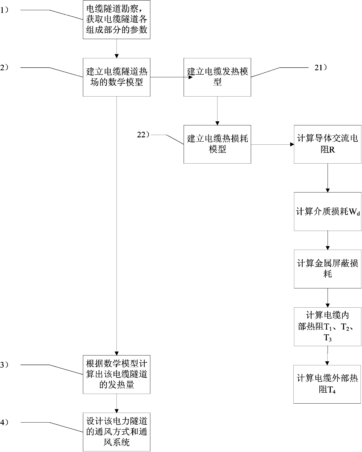
[0071] A heat dissipation method based on a cable tunnel thermal field model without a slot box, comprising the following steps:

[0072] 1) Cable tunnel investigation, to obtain the parameters of each component of the cable tunnel;

[0073] 2) Establish a mathematical model of the thermal field of the cable tunnel;

[0074] 3) Calculate the calorific value of the cable tunnel according to the mathematical model;

[0075] 4) Design the ventilation mode and ventilation system of the power tunnel.

[0076] The thermal resistance is obtained by R=d / KA, where R is the thermal resistance, d is the thickness of the thermal conductor, A is the cross-sectional area of ​​the thermal conductor, and K is the thermal conductivity.

[0077] The mathematical model establishment of the cable tunnel heat field in the described step 2) includes the following sub-steps:

[0078] 21) Establish cable heating model:

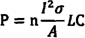
[0079] The heat dissipation power of the n-circuit cable is:

[0080] ...


PUM


Abstract

The invention relates to a heat dissipation method based on a slotless box cable tunnel thermal field model. The method includes the following steps of (1) exploring a cable tunnel to obtain parameters of all components of the cable tunnel, (2) building a mathematical model of a cable tunnel thermal field, (3) working out the calorific value of the cable tunnel according to the mathematical model and (4) designing the ventilation mode and the ventilation system of the electric power tunnel. Compared with the prior art, the heat dissipation method has the advantages of being effective and accurate.

Description

technical field [0001] The invention relates to the field of electric power transmission, in particular to a heat dissipation method based on a heat field model of a cable tunnel without a slot box Background technique [0002] In order to solve the increasingly serious power supply problem, it is planned to use the large channel under construction to lay 220kV power cables. For the section of the river-crossing tunnel, the current preliminary plan is to use the divided cable channels in each tunnel as high-voltage cable tunnels and lay 220kV power cables. [0003] The laying of high-voltage power cables was not considered in the original plan of the tunnel, so the heat generation of power cables was not considered in the design of tunnel ventilation and heat dissipation. The power cable generates heat during long-term operation, resulting in an increase in the temperature of the cable channel, which may affect the safe operation of other equipment in the same space in the ...

Claims


Application Information

Patent Timeline
IPC IPC(8): E21F1/02
Inventor 李红雷
Owner SHANGHAI MUNICIPAL ELECTRIC POWER CO
Why Eureka
Try Eureka