
Electrostatic partricle sensor

a technology of partricle and sensor, applied in the field of electrostatic particle sensor, can solve the problems of unavoidable corruption of measuring results, complex design, interference,

Inactive Publication Date: 2009-12-03
ROBERT BOSCH GMBH
View PDF8 Cites 23 Cited by
  • Summary
  • Abstract
  • Description
  • Claims
  • Application Information

AI Technical Summary

Benefits of technology

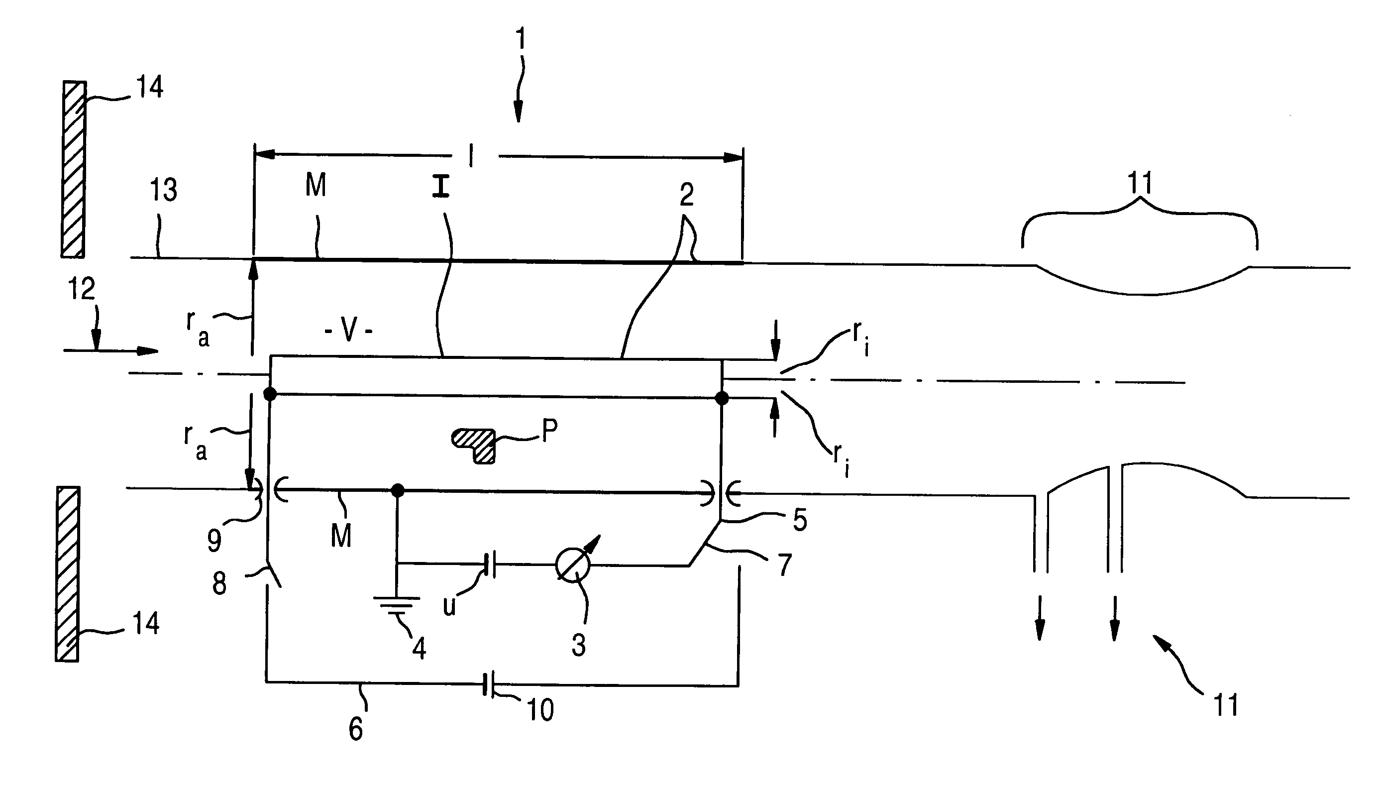
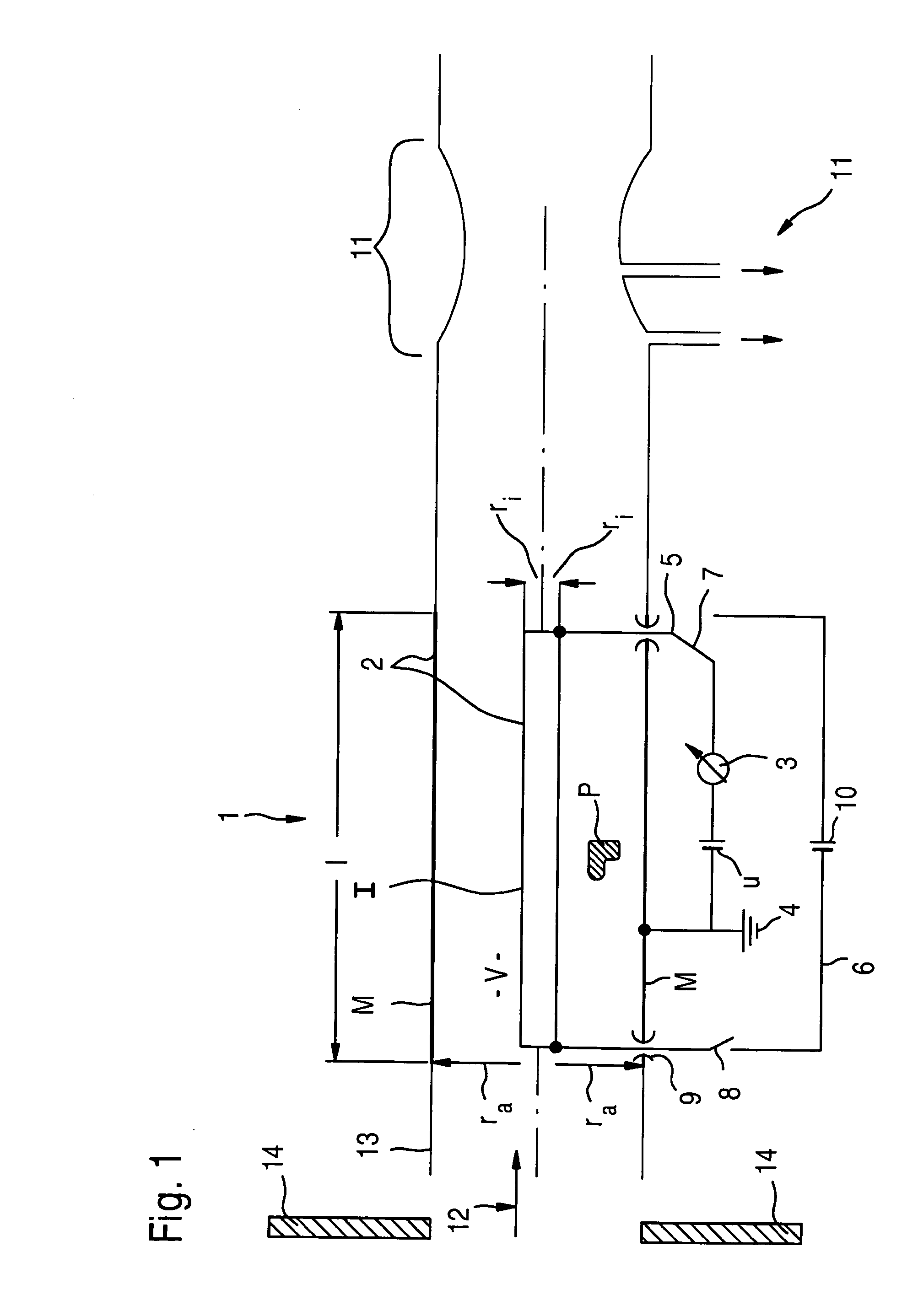
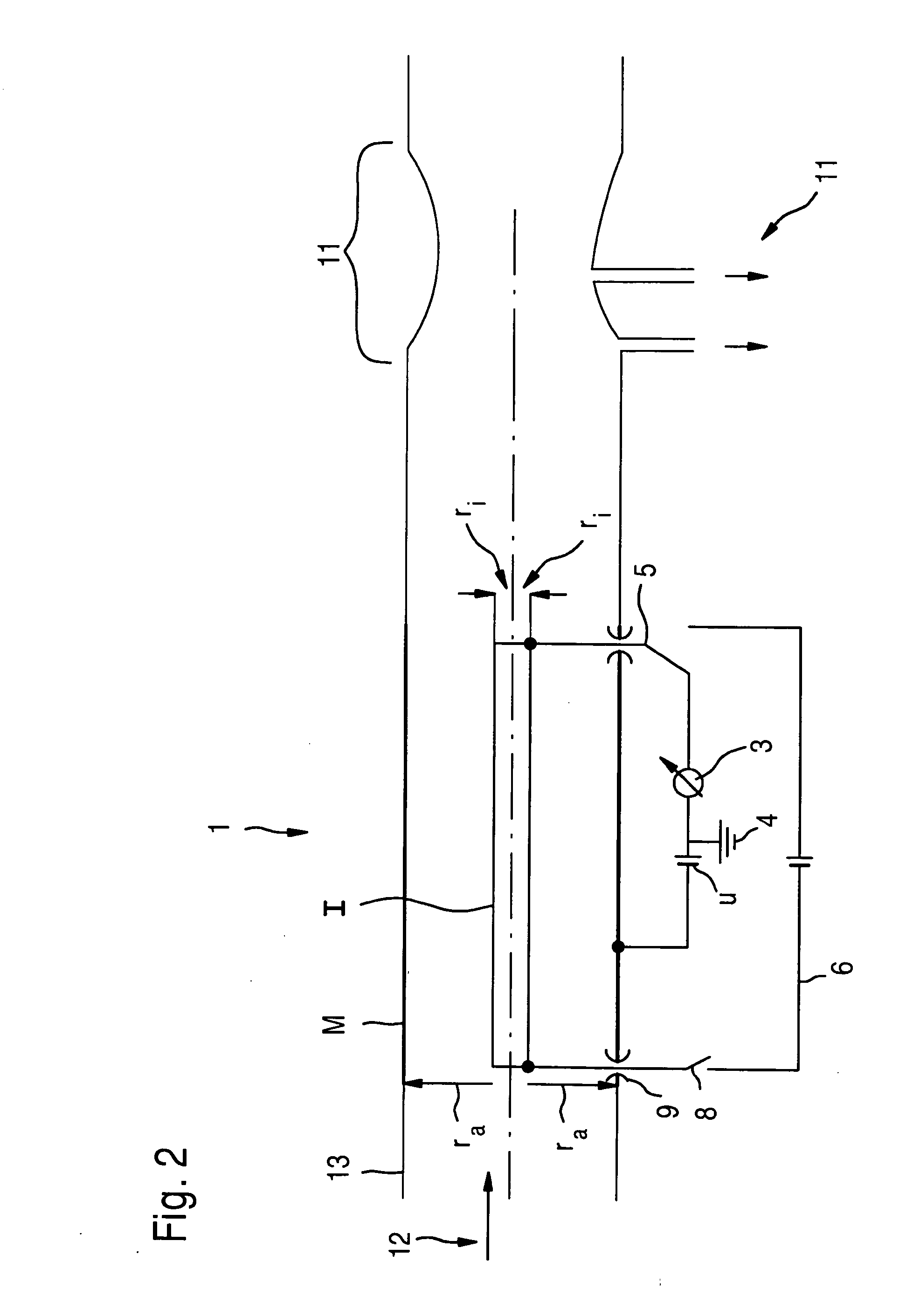
[0011]This approach is based on the finding that particles, in particular soot particles, having a different electrical mobility and thus a different mass and size, which are directly related thereto, may be detected by varying the electric field without having to modify the effective volume flow rate between the two measuring electrodes.
[0013]It is considered as particularly advantageous here if the particle sensor is designed as a cylindrical capacitor, so that it is possible to accurately establish the volume that is effective for particle determination of the measuring gas by using defined geometric parameters. In addition, a cylindrical capacitor offers the possibility to detect particles having less mobility, i.e., greater mass, due to the radial dependency of the electric field contained therein for identical exterior dimensions and applied potential.
[0015]Therefore, a gas velocity measuring device which is most preferably designed as a non-invasive measuring device, a Venturi nozzle for example, is provided in a preferred specific embodiment. This makes it possible to determine the gas velocity without or at least without significant interference in the gas flow, which in turn has a positive effect on the measuring accuracy of the particle sensor. The measuring device may be situated either upstream or downstream from the electrode system in the direction of the gas flow.
[0017]In contrast to example embodiments in which the effective volume flow is merely assumed on the basis of a presumed gas velocity, preferably a mean gas velocity, these example embodiments make it possible to further reduce system-related measuring errors by directly taking into account any velocity changes in the gas flow.
[0018]Of course, it is basically also possible to execute the measuring method through the sensor volume without directly detecting the velocity of the measuring gas flow; however, this saving is obtained through a comparatively lower measuring accuracy of the respective measuring sensor.
[0022]Furthermore, deposits in the measuring system could be removed in order to avoid measuring errors by using a heating device, preferably by burning them.

Problems solved by technology

However, these methods have the disadvantage that they are subject to interference due to particle deposits on the sensor elements.
Some of these methods have a complex design and have the additional disadvantage that the measurement does not take place directly in the exhaust gas system and therefore corruption of the measuring result is unavoidable, partly as a function of the age of the measuring gas due to chemical processes taking place in the measuring gas.
However, it is disadvantageous in both of these measuring methods that only particles having certain sizes which are in the range ascertainable by the particular sensor used based on the physical interrelations of the particular measuring method may be detected.
Complete quality information about the measured exhaust gas is thus not possible to obtain using these sensors.

Method used


Image

  • Electrostatic partricle sensor
  • Electrostatic partricle sensor
  • Electrostatic partricle sensor

Examples


Embodiment Construction

[0027]FIGS. 1 and 2 show two exemplary, symbolically represented configurations of electrostatic sensors for measuring particles in aerosols, in particular for measuring soot particles in exhaust gases, the exhaust gases being preferably exhaust gases of diesel engines.

[0028]Such sensors may be provided as sturdy measuring devices for analyzing soot particles directly in the exhaust gas system so that, on the one hand, they are suitable to be operated in a shop and, on the other hand, for direct installation in a respective vehicle for improving the exhaust gas quality and basically for improving the engine properties.

[0029]Another possible area for the use of such sensors is the field of heating technology. Here also, mobile as well as immobile applications may be provided. In mobile applications, the instantaneous exhaust gas values of a heating system may be determined, for example. In immobile applications, a direct effect on the regulation process of the heating system is conce...


PUM


Abstract

An electrostatic particle sensor for sensing particles in exhaust gases includes: a lateral surface electrode having an effective flow volume, a gas flow to be tested flowing through it; an inner electrode situated inside the lateral surface electrode; and a voltage source which is in an electrically conducting connection with both electrodes. A potential which is dependent on the gas flow rate per time unit through the effective flow volume is impressed upon the voltage source.

Description

BACKGROUND OF THE INVENTION[0001]1. Field of the Invention[0002]The present invention relates to an electrostatic particle sensor.[0003]2. Description of Related Art[0004]The environmental pollution by fine particulate matter, in particular by soot particles which are produced during combustion processes of petroleum products, is on the increase. By improving the combustion technology of petroleum products, such as engine and heating system technologies, the particulate residues which remain from the oxidation process are considered increasingly critical for the environment due to highly reduced particle sizes.[0005]Moreover, it is possible to evaluate the quality of the oxidation process based on the number and size of the particles in a defined exhaust gas volume. For example, it is known to use optical measuring methods for determining the exhaust gas quality. However, these methods have the disadvantage that they are subject to interference due to particle deposits on the sensor...

Claims


Application Information

Patent Timeline
IPC IPC(8): G01N27/60G01N27/62
CPCG01N1/2247G01N2001/2223G01N15/0266
Inventor WILHELM, STEFAN
Owner ROBERT BOSCH GMBH
Learn More