Pressure-bearing vaporization heat dissipating device

A radiator and vaporization chamber technology, applied in the field of heat dissipation, can solve the problems of large space occupation, installation of cooling fans, large area, etc., and achieve the effects of simple structure, high heat dissipation efficiency and small volume

Inactive Publication Date: 2014-12-10
梁伟龙
View PDF0 Cites 1 Cited by
  • Summary
  • Abstract
  • Description
  • Claims
  • Application Information

AI Technical Summary

Problems solved by technology

[0002] Nowadays, mainstream water-cooled radiators all have some common disadvantages, such as large cooling fins, complex structure and large number of cooling pipes, large space occupation, and even need to install cooling fans, high manufacturing cost

Method used


Image

  • Pressure-bearing vaporization heat dissipating device
  • Pressure-bearing vaporization heat dissipating device

Examples


Embodiment Construction

[0018] Below in conjunction with accompanying drawing, the present invention will be further described. The following embodiments use a water pump as a power source to enable those skilled in the art to better understand the present invention, and do not limit the present invention in any way.

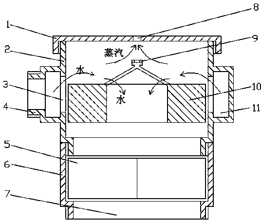
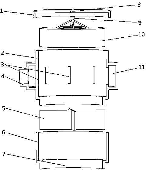
[0019] The embodiment of pressure-bearing vaporization radiator of the present invention: as figure 1 As shown, the pressure-bearing vaporization radiator includes a shell, a liquid inlet (3), a relatively liquid outlet (7), and an exhaust port (8). Compared with the liquid outlet (7), the liquid inlet (3) has a smaller geometric size or greater fluid resistance, and the exhaust port (8) is located on the upper part of the liquid outlet (7). The housing is composed of a vaporization chamber (2) and a diversion chamber (6). The vaporization chamber (2) is located on the upper part of the diversion chamber (6). The vaporization chamber (2) and the diversion chamber (6) communicate with ...


PUM


Abstract

The invention discloses a pressure-bearing vaporization heat dissipating device. Compared with a liquid outlet (7), a liquid inlet (3) is smaller in geometric dimension and larger in fluid resistance. After a water pump pumps liquid out of the liquid outlet (7), liquid at the position of a liquid distributing flow channel (11) cannot flow back to a vaporization chamber (2) from the liquid inlet (3) for supplementation in time, and the pressure in the vaporization chamber (2) will be lower than that in the liquid distributing flow channel (11). After entering the low-pressure vaporization chamber (2) through the liquid inlet (3), high-temperature high-pressure liquid is rapidly vaporized, steam is discharged out from an exhaust port (8), and the liquid which is not vaporized is discharged out through the liquid outlet (7). The pressure-bearing vaporization heat dissipating device is particularly suitable for heat dissipation of high-temperature liquid in a pressure-bearing system. Compared with an ordinary water cooling type heat dissipating device, the pressure-bearing vaporization heat dissipating device does not need cooling fins quite large in area, or complicated liquid channels arranged in the heat dissipating device or fans and is small in size, simple in structure and high in heat dissipating efficiency; in addition, the pressure-bearing vaporization heat dissipating device is also suitable for the field of sea water desalination, the field of oil-water separation and the like.

Description

technical field [0001] The invention relates to a heat dissipation technology, in particular to the technology of utilizing liquid vaporization to achieve the purpose of heat dissipation. Background technique [0002] Nowadays, mainstream water-cooled radiators all have some common disadvantages, such as large-area cooling fins, complex structures and a large number of cooling pipes, taking up a lot of space, and even need to install cooling fans, resulting in high manufacturing costs. Especially for high-power radiators, these shortcomings are even more prominent. Contents of the invention [0003] The object of the present invention is to overcome the above-mentioned shortcomings of the heat sink, and provide a pressure-bearing vaporization heat sink with a simple structure and high heat dissipation efficiency. [0004] The technical solution adopted by the present invention to solve the technical problem is to provide a pressure-bearing vaporization radiator, including...

Claims


Application Information

Patent Timeline
Patent Type & Authority Applications(China)
IPC IPC(8): F28D21/00
Inventor 梁伟龙
Owner 梁伟龙
Why Eureka
Try Eureka