Short circuit grounding wire device with locking function

A technology of short-circuiting grounding wires and grounding wires, which is applied in the field of power systems, can solve problems such as death, equipment burnout, and operator arc burns, and achieve the effect of avoiding vicious accidents and preventing accidents of closing and power transmission

Active Publication Date: 2014-12-10
STATE GRID CORP OF CHINA +1
View PDF10 Cites 13 Cited by
  • Summary
  • Abstract
  • Description
  • Claims
  • Application Information

AI Technical Summary

Problems solved by technology

[0002] The short-circuit grounding wire is an indispensable safety tool for power equipment maintenance. However, once there is a mistake in the operation of adding a short-circuit grounding wire, such as adding a short-circuit grounding wire to a live power equipment by mistake, it will cause serious damage to the high-voltage equipment. Metallic grounding short circuit, resulting in huge short circuit current and high temperature arc, leading to serious accidents such as instant burning of on-site equipment, arc burns and even death of operators
[0003] With the deepening of the anti-misoperation management system and the advancement of technology, misoperation accidents in the power industry have been decreasing year by year. However, many vicious misoperation accidents have not been fundamentally eliminated. happened
The short-circuited grounding wire on the live wire not only causes serious equipment damage, but also causes extremely serious personal injury. However, there is still no technical solution to this problem
Chinese patent CN201210398449 proposes an anti-misoperation electric power grounding wire. This technology can prevent "hanging the equipment end first and then the grounding end" by setting an interlocking device between the grounding chuck and the grounding end chuck of the conventional short-circuit grounding wire. In case of illegal operation, but for the situation that the grounded equipment is called suddenly, the equipment nameplate is wrong, the electroscope is faulty, etc., the technology is completely ineffective. It is particularly necessary to hang a short-circuit grounding wire

Method used


Image

  • Short circuit grounding wire device with locking function
  • Short circuit grounding wire device with locking function

Examples


Embodiment

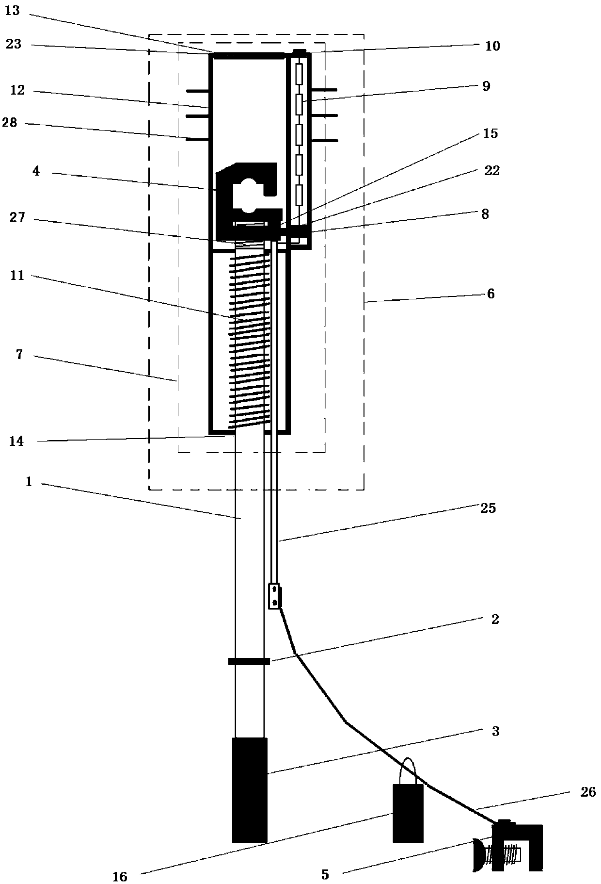
[0020] See attached figure 1 , which is a structural schematic diagram of the first embodiment of the present invention. Wherein the live warning device 6 is made up of an anti-misoperation locking device 7. The anti-misoperation locking device is composed of electromagnet 8, impedance element 9, electrode 10, spring 11, insulating housing 12 and other components. Electromagnet 8, impedance element 9 and spring 11 are located inside the insulating housing, and spring 11 is installed Located between the grounding chuck 4 and the bottom of the insulating housing 12, the top and bottom of the insulating housing 12 are respectively provided with holes 13, 14 for the axial movement of the grounding chuck 4 and the operating rod, and the side of the grounding chuck 4 There is a bayonet 15, which corresponds to the position of the armature 22 of the electromagnet 8, and the electrode 10 is located on the top of the insulating case 12, and is connected in series with the impedance el...


PUM


Abstract

The invention relates to a short circuit grounding wire device with a locking function. The short circuit grounding wire device comprises an operation rod (1), a grounding chuck (4), a grounding wire guide-out end (25), a grounding lead (26) and a grounding end chuck (5). The grounding chuck (4) is connected with the grounding lead (26) through the grounding wire guide-out end (25). The grounding lead (26) is connected with the grounding end chuck (5). The side, close to the grounding chuck (4), of the operation rod (1) is provided with an electrified pre-warning device (6). The pre-warning device (6) comprises a locking device (7) for preventing misoperation. Locking can be performed through the locking device (7) when grounding misoperation occurs, and personal safety of operators is guaranteed. Compared with the prior art, the short circuit grounding wire device is safe and reliable, convenient to operate, and the like.

Description

technical field [0001] The invention relates to the field of power systems, in particular to a short-circuit grounding wire device with a blocking function. Background technique [0002] The short-circuit grounding wire is an indispensable safety tool for power equipment maintenance. However, once there is a mistake in the operation of adding a short-circuit grounding wire, such as adding a short-circuit grounding wire to a live power equipment by mistake, it will cause serious damage to the high-voltage equipment. Metallic grounding short circuit produces extremely large short circuit current and high temperature arc, leading to serious accidents such as instant burning of on-site equipment, arc burns and even death of operators. [0003] With the deepening of the anti-misoperation management system and the advancement of technology, misoperation accidents in the power industry have been decreasing year by year. However, many vicious misoperation accidents have not been fun...

Claims


Application Information

Patent Timeline
Patent Type & Authority Applications(China)
IPC IPC(8): H01R4/66G01R31/02
Inventor 周徐达冷超阴春晓刁冠勋苏丰王长春
Owner STATE GRID CORP OF CHINA
Why Eureka
Try Eureka