equipment for filtering fluids

A technology for filtering fluid and equipment, applied in the direction of filtration and separation, fixed filter elements, chemical instruments and methods, etc., can solve a large number of problems, and achieve the effect of simple design, compact space, and compact size

Inactive Publication Date: 2017-09-05
马格自动化有限责任公司
View PDF5 Cites 0 Cited by
  • Summary
  • Abstract
  • Description
  • Claims
  • Application Information

AI Technical Summary

Problems solved by technology

For example, in molten recyclable material, large amounts of this contamination can be present

Method used


Image

  • equipment for filtering fluids
  • equipment for filtering fluids
  • equipment for filtering fluids

Examples


Embodiment Construction

[0049] In the drawings, the same parts are marked by the same reference numerals, and in some drawings, some reference numerals are omitted for the sake of clarity. Components described individually according to the preferred embodiments of the present invention can be combined arbitrarily in a manner well known to those skilled in the art. The illustrated embodiments are non-limiting in terms of various combinations.

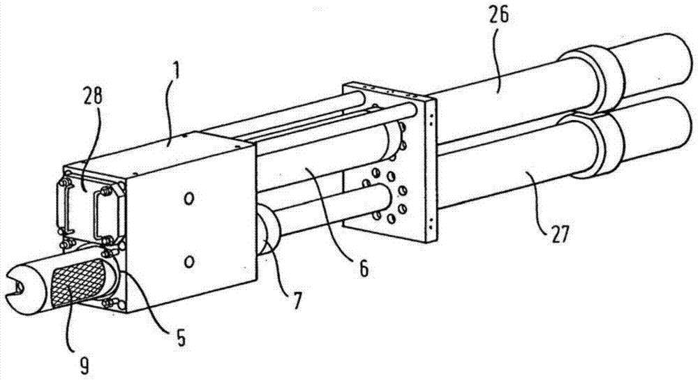
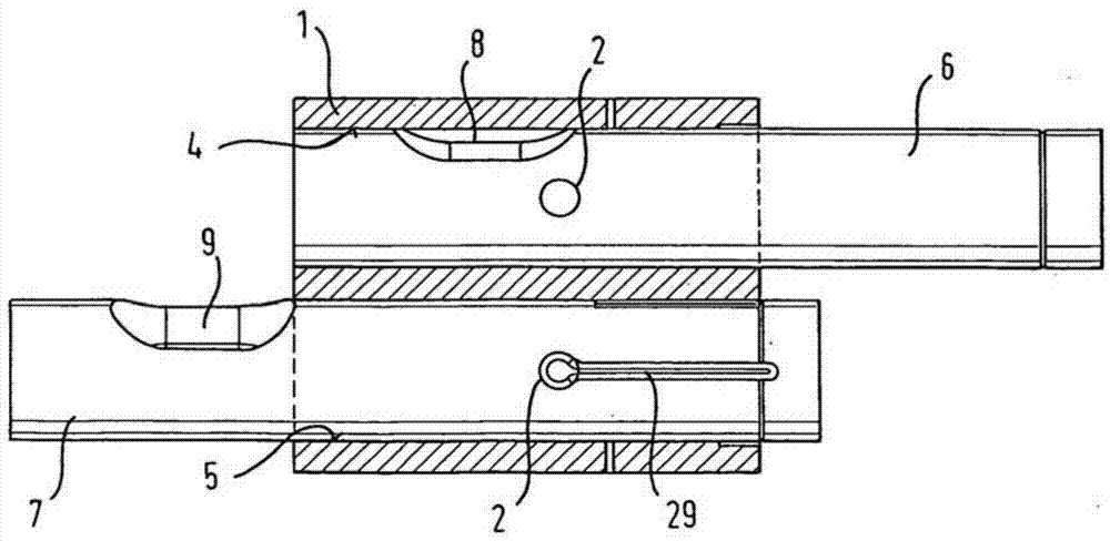
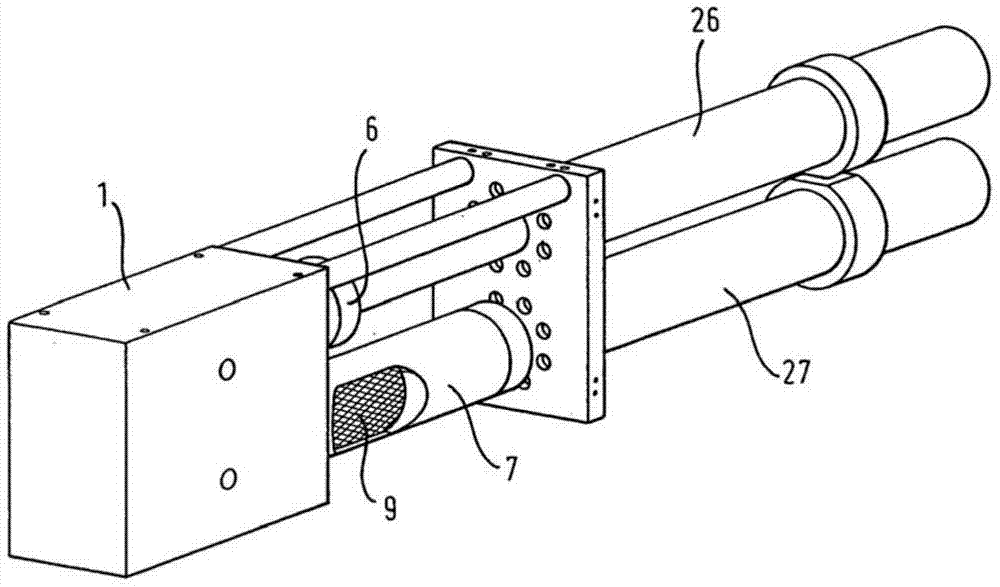
[0050] figure 1 A perspective view of an apparatus for filtering fluid according to a first preferred embodiment of the present invention is shown. In particular, the shown apparatus is used for filtering thermoplastic polymer melts and comprises a housing 1 with bolts 6, 7 which can be inserted into the holes 4, 5 of the housing 1 (the upper hole 4 is in the figure 1 (not visible in ) is movable in a fluid-tight manner, ie axially displaceable and / or radially rotatable. Each bolt 6, 7 comprises at least one filter unit 8, 9 with an inflow side and an outflo...


PUM


Abstract

The invention relates to a device for filtering thermoplastic melts, comprising a housing (1) having at least one fluid inlet channel (2) and at least one fluid outlet channel (3) and having fluid At least two holes (4, 5) in which the inlet channel and the fluid outlet channel are fluidly connected. In each hole (4, 5) a corresponding bolt (6, 7) is axially displaceable, radially rotatable and mounted in a fluid-tight manner, each said bolt being provided with a filter unit (8, 9), said filter unit (8, 9) has an inflow side and an outflow side. Each of said bolts is movable at least between a filtering position and a backflushing position, and each bolt is movable into a filling position in which fluid flows from the corresponding filter unit through the corresponding cleaning fluid channel (12, 13) The outflow side flows to storage cavities (14, 15) formed by movement of respective bolts in respective holes (4, 5). When the corresponding hole is moved to the backflush position, the fluid flows again through the corresponding filter unit to the at least one backflush channel and out of the housing.

Description

technical field [0001] The present invention relates to a device for filtering fluids, and more particularly to a device for filtering thermoplastic polymer melts, the device comprising a housing according to the preamble of claim 1 having at least one fluid inlet channel and at least one fluid outlet passage and having at least two mutually parallel and spaced apart holes in fluid communication with the fluid inlet passage and the fluid outlet passage respectively, wherein each hole is received therein in a fluid-tight manner to be movable (i.e. Axially displaceable and / or radially rotatable) bolts, each of which is provided with a filter unit having an inflow side and an outflow side, wherein each of said bolts can be at least in a first filter position and a second backflush position, in which the inflow side and outflow side of the filter unit are in fluid communication with the fluid inlet channel and the fluid outlet channel respectively, and in the second backflush posi...

Claims


Application Information

Patent Timeline
Patent Type & Authority Patents(China)
IPC IPC(8): B01D29/60B29B13/10B29C45/58B29C47/68
CPCB29C48/2554B29C48/273B29C48/6912B01D29/13B01D29/52B01D29/66
Inventor H·波尔
Owner 马格自动化有限责任公司
Why Eureka
Try Eureka