Machining control device, laser machining device, and laser control method
A control device and laser processing technology, applied in laser welding equipment, metal processing equipment, manufacturing tools, etc., can solve the problem of inability to laser process workpieces, and achieve the effect of high-efficiency laser processing
- Summary
- Abstract
- Description
- Claims
- Application Information
AI Technical Summary
Problems solved by technology
Method used
Image
Examples
Embodiment approach 1
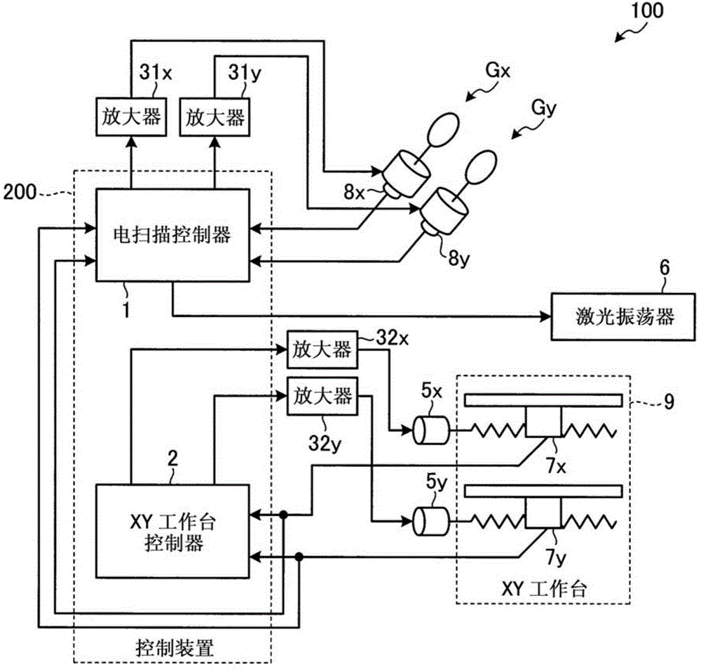
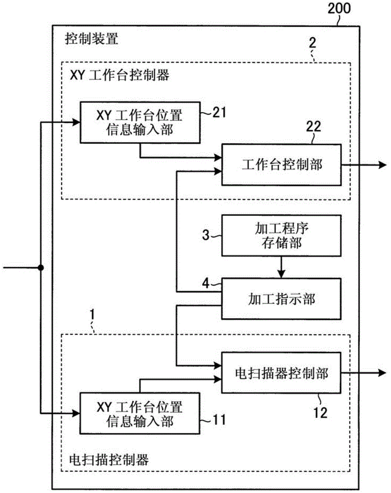
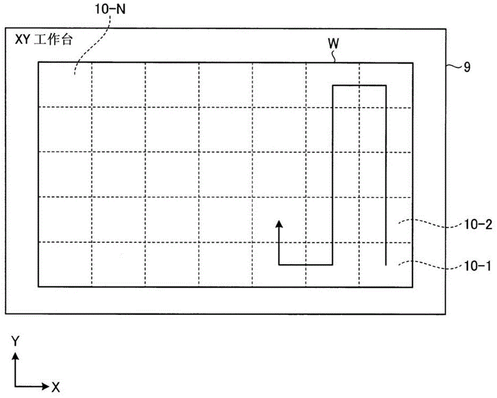
[0030] figure 1 It is a figure which shows the structure of the laser processing apparatus concerning Embodiment 1. The laser processing apparatus 100 is an apparatus for performing hole processing for forming a through hole or the like of a printed wiring board on a workpiece (work to be processed) W described later. The laser processing apparatus 100 of this embodiment moves the XY table 9 in a stepwise manner, and when the galvano region becomes the desired coordinates (target coordinates) by moving the XY table 9, the XY table 9 stops until the XY table 9 stops. So far, laser processing has been performed using coordinated control. Then, when the XY table 9 stops and the galvano area becomes the desired coordinates, the laser processing apparatus 100 performs laser processing in a state where the XY table 9 is stopped.
[0031] The laser processing device 100 has: a control device (processing control device) 200, amplifiers 31x, 31y, 32x, 32y, motors 5x, 5y, XY table 9, ...
Embodiment approach 2
[0096] Next, use Figure 10 and Figure 11 Embodiment 2 of the present invention will be described. In Embodiment 2, laser processing is performed by the same processing procedure as in Embodiment 1, using the rear end portion in the moving direction in the processing area as the coordinated control area.
[0097] Figure 10 It is a figure for demonstrating the process procedure of the laser processing process concerning Embodiment 2. Here, a case where laser processing is performed in the order of the processing area 10 - 1 to the processing area 10 - 6 will be described. In this embodiment, the laser processing apparatus 100 performs the movement processing and cooperative control processing of the XY table 9 similarly to the case of Embodiment 1. As shown in FIG.
[0098] The cooperative control area of this embodiment is the rear end part of the movement direction in a processing area. exist Figure 10 , each cooperative control area of the processing areas 10-2 ...
Embodiment approach 3
[0106] Next, use Figure 12 , Embodiment 3 of the present invention will be described. In Embodiment 3, laser processing using cooperative control is started when the processing area enters the galvano area. Then, after the laser processing in the cooperative control area is completed, the laser processing is temporarily stopped, and after the movement of the XY table 9 is completed, the laser processing other than the cooperative control area is performed.
[0107] Figure 12 It is a figure which shows the processing procedure of the laser processing process concerning Embodiment 3. exist Figure 12 , a cross-sectional view of the workpiece W is shown. Figure 12 The shown process (S31) is the same process as the process (S11) demonstrated using FIG. 6-2 of Embodiment 1. FIG. That is, when the processing area 82 on the workpiece W is outside the galvano area 81 ( S31 ), laser processing is not performed.
[0108] Then, when the processing area 82 on the workpiece W ente...
PUM
 Abstract
Description
Claims
Application Information
 - R&D
- Intellectual Property
- Life Sciences
- Materials
- Tech Scout
- Unparalleled Data Quality
- Higher Quality Content
- 60% Fewer Hallucinations
Browse by: Latest US Patents, China's latest patents, Technical Efficacy Thesaurus, Application Domain, Technology Topic, Popular Technical Reports.
© 2025 PatSnap. All rights reserved.Legal|Privacy policy|Modern Slavery Act Transparency Statement|Sitemap|About US| Contact US: help@patsnap.com


