
Device for introducing a release agent into a hollow workpiece

A hollow workpiece and release agent technology, applied in metal processing equipment, welding equipment, laser welding equipment, etc., can solve problems such as difficulty, uneconomical application, technical trouble, etc., and achieve the effect of not damaging productivity

Pending Publication Date: 2021-10-29
TRUMPF WERKZEUGMASCHINEN GMBH & CO KG
View PDF6 Cites 0 Cited by
  • Summary
  • Abstract
  • Description
  • Claims
  • Application Information

AI Technical Summary

Problems solved by technology

However, this solution cannot be applied economically and it is technically complex and difficult to position the nozzle of the device for applying a release agent disclosed in said document in the workpiece

Method used


Image

  • Device for introducing a release agent into a hollow workpiece
  • Device for introducing a release agent into a hollow workpiece
  • Device for introducing a release agent into a hollow workpiece

Examples


Embodiment Construction

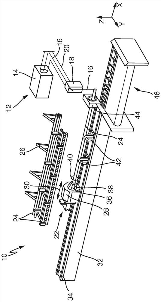
[0043] figure 1 A system for machining hollow workpieces is shown in a schematically simplified form, which is generally designated by the reference numeral 10 .

[0044] The system 10 first includes a laser processing machine 12 . The laser processing machine 12 includes a laser beam source 14 for generating a laser beam 16 , a laser cutting head 18 and a beam guidance device 20 for guiding the laser beam 16 from the laser beam source 14 to the laser cutting head 18 .

[0045] The system 10 also includes a supply device 22 for laterally supplying a workpiece 24 to be processed, in particular cut, by the laser processing machine 12 by means of the generated laser beam 16 . The supply device 22 comprises holding means 28 for holding and moving the workpiece 24 so that the workpiece can be laser cut. The holding device 28 is motor-driven and can move back and forth in a feed direction (X-direction) 30 . The supply device 22 also includes a machine bed 32 with a guide rail 34 ...


PUM


Abstract

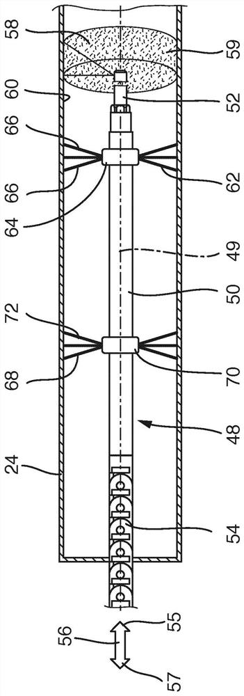
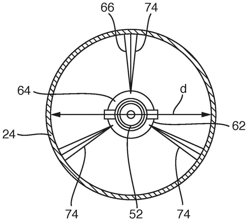
A device for introducing a release agent into a hollow workpiece before or while the workpiece is machined by means of a laser machining tool, the device comprising an introduction section with a nozzle for dispensing the release agent and with a centring element which is arranged on the introduction section and which serves for centring the introduction section within the hollow workpiece.

Description

technical field [0001] The invention relates to a device for introducing a release agent into a workpiece before or during machining of a hollow workpiece by means of a laser processing machine. The invention also relates to an associated loading station, an associated system and an associated method. Background technique [0002] During laser machining (in particular laser cutting) of hollow workpieces such as tubes, cutting debris generated during the machining accumulates on the inside of the workpiece, especially the tube. These contaminations on the inner side of the workpiece can only be removed in a difficult, complex and expensive manner by subsequent cleaning. [0003] By using a release agent, the adhesion of cutting chips can be reduced and the subsequent cleaning of the workpiece can be carried out more easily, quickly and at low cost. However, the usual "manual" introduction of release agents is time-consuming and the laser processing machine can be heavily co...

Claims


Application Information

Patent Timeline
Patent Type & Authority Applications(China)
IPC IPC(8): B05B13/06B23K26/70
CPCB05B13/06B05B13/0627B23K26/702B23K26/16B23K26/38B23K2101/06B23K26/142B23K26/146B23K26/147
Inventor F·雅施K·吕茨
Owner TRUMPF WERKZEUGMASCHINEN GMBH & CO KG
Learn More