
Laser processing method, laser processing device and cable harness production method

a laser processing and laser processing technology, applied in the direction of soldering devices, conductors, auxilary welding devices, etc., can solve the problems of requiring an extremely expensive system, affecting the quality of the cable, so as to achieve the effect of efficient laser processing of the lateral surfaces of objects

Inactive Publication Date: 2009-09-10
SUMITOMO ELECTRIC IND LTD
View PDF24 Cites 0 Cited by
  • Summary
  • Abstract
  • Description
  • Claims
  • Application Information

AI Technical Summary

Benefits of technology

The present invention provides a laser processing method that can effectively remove shielding from cables without causing damage to the inside of the cable. The method uses a laser light that is radiated onto the cables and the laser light is reflected by reflecting members on a laser-processing stage. The laser light is then directed onto the lateral surfaces of the cables using a reflecting member. The method can be carried out with a single control mechanism and laser power control mechanism, which is less expensive than previous methods. The invention also provides a laser processing device and a cable harness production method that can efficiently carry out laser processing.

Problems solved by technology

However, in the case of radiating laser light of an intensity that enables shielding of lateral surfaces to be adequately removed at locations easily reached by the laser light, it not only severs the shielding but also causes damage to the inside of the cable.
However, in order to carry out laser processing on an object in the manner of a cable harness by changing laser light intensity by mechanical or optical control, a control mechanism and laser power control mechanism capable of high-speed position detection are required, thus resulting in the problem of requiring an extremely expensive system.

Method used


Image

  • Laser processing method, laser processing device and cable harness production method
  • Laser processing method, laser processing device and cable harness production method
  • Laser processing method, laser processing device and cable harness production method

Examples


first embodiment

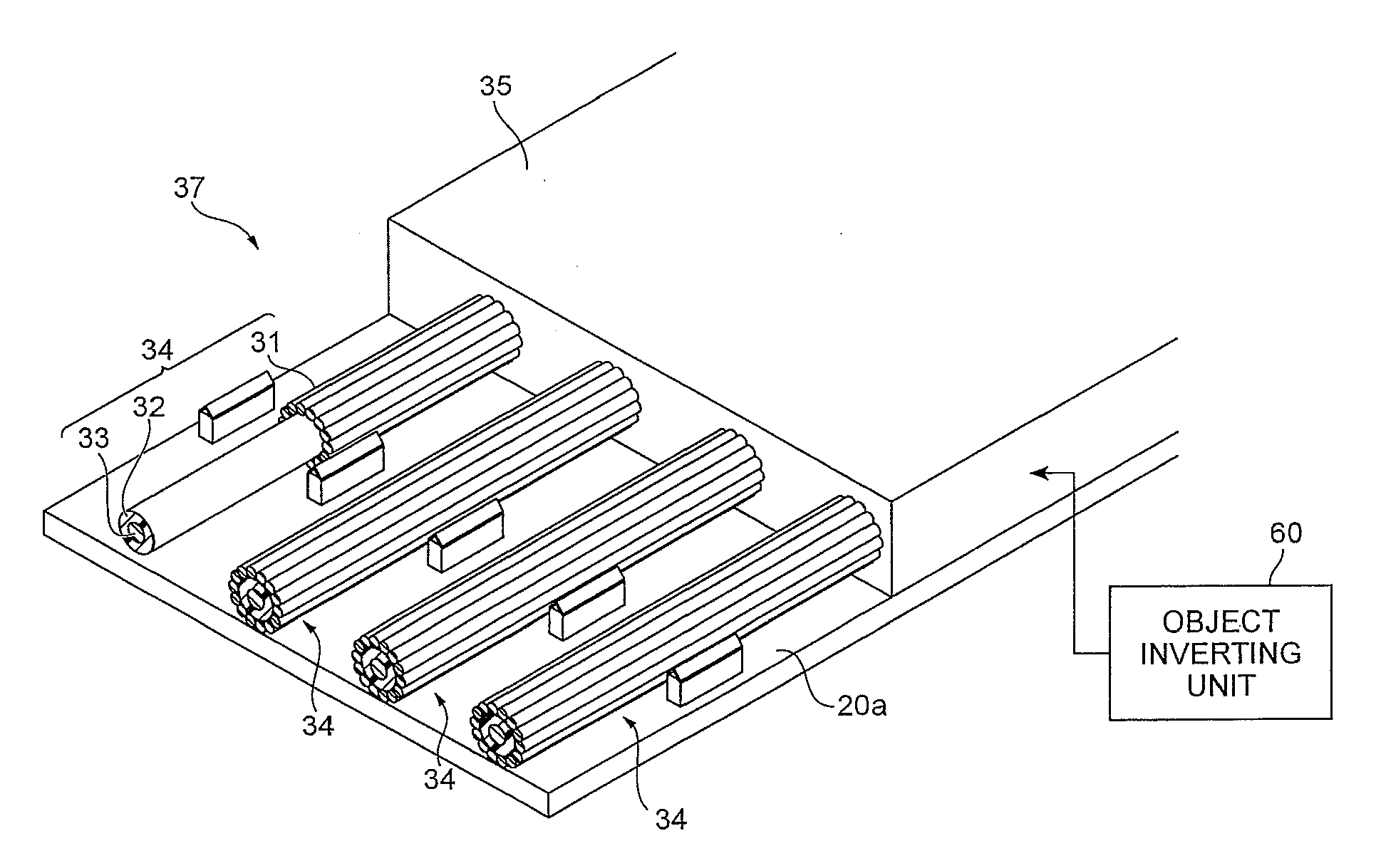
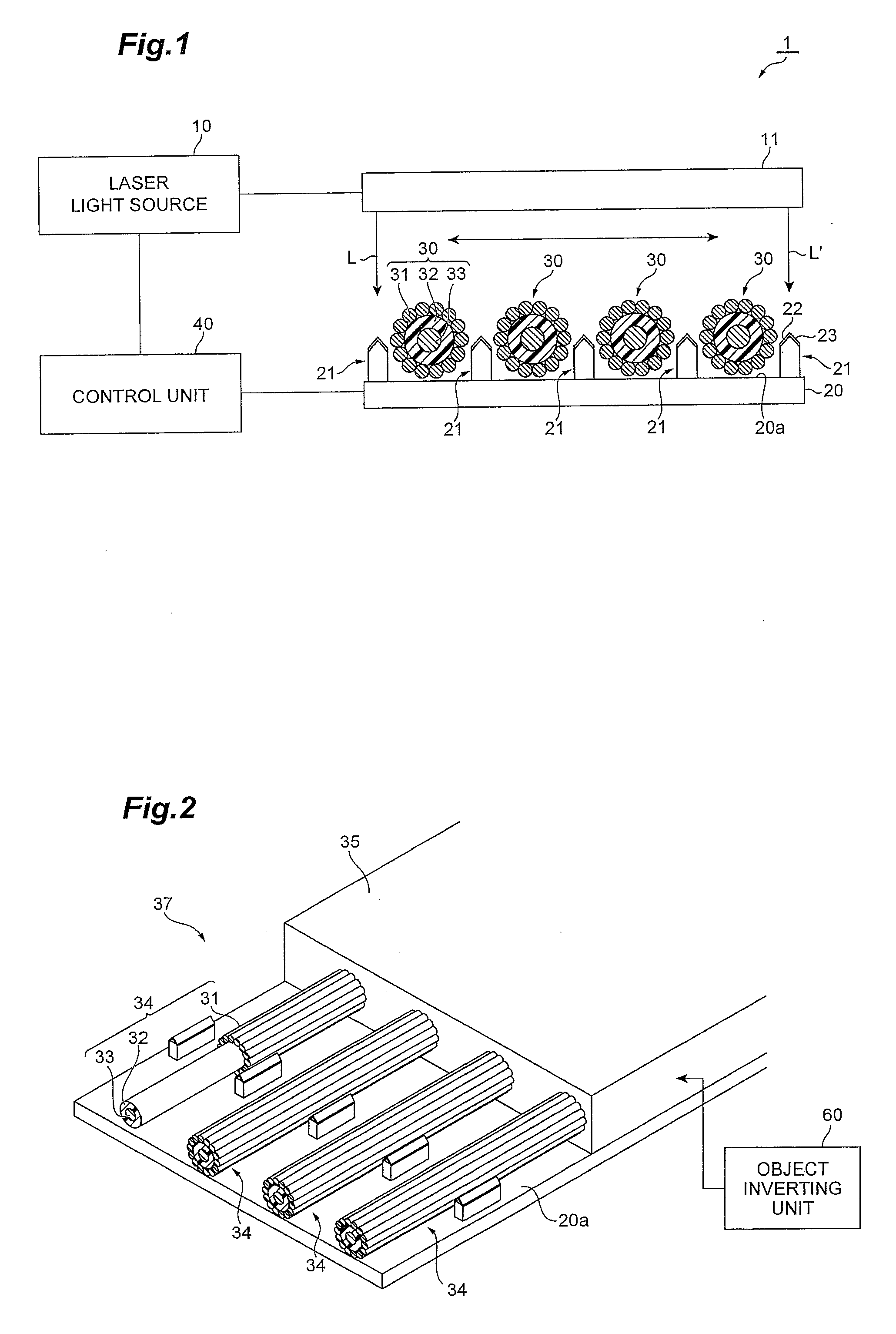
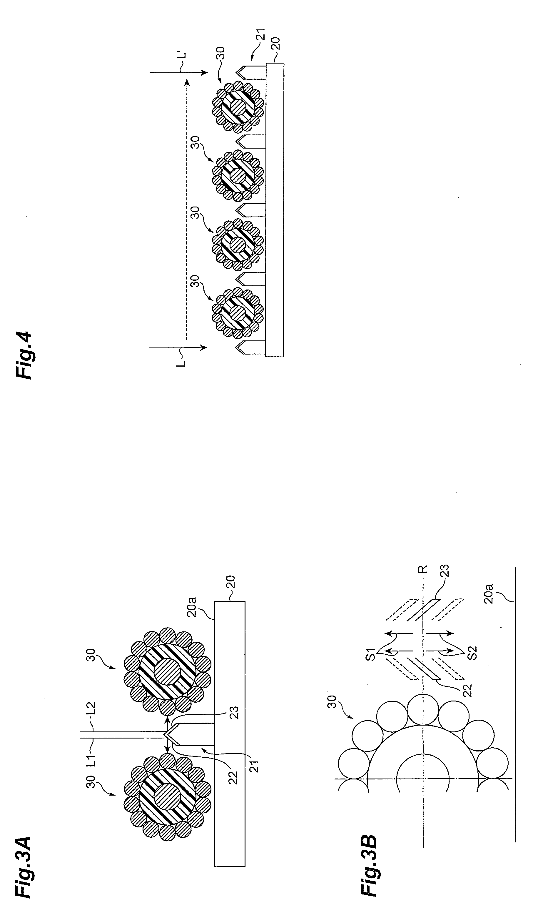
[0039]The following provides an explanation of a first embodiment of the laser processing device according to the present invention. FIG. 1 is a drawing showing the configuration of a laser processing device 1 according to the present embodiment. The laser processing device 1 shown in FIG. 1 is provided with a laser light source 10, radiation optics 11, a laser-processing stage 20, reflecting members 21 and a control unit 40, and processes objects 30 arranged on the laser-processing stage 20. A height adjustment unit, for adjusting the height of the reflecting surfaces 22 and 23 of the reflecting members 21 from the installation surface 20a of the laser-processing stage 20, is constituted by the laser-processing stage 20 and the control unit 40. The laser processing device 1 further comprises an object inverting unit 60 for changing the surfaces of objects that directly face the radiation optics 11.

[0040]The laser light source 10 outputs laser light, and is a YAG laser light source ...

second embodiment

[0060]The following provides an explanation of a second embodiment of the laser processing device according to the present invention. FIG. 8 is a drawing showing the configuration of the laser-processing stage 20, the reflecting members 21, a pump 50 and suction tubes 51 in the laser processing device according to the present embodiment. The laser light source 10, the radiation optics 11 and the control unit 40 are the same as in the first embodiment. A suction unit is constituted by the pump 50 and the suction tubes 51. The laser processing device 2 according to the second embodiment differs from the laser processing device 1 according to the first embodiment with respect to the suction tubes 51 being arranged by providing openings in the laser-processing stage 20, and air on the laser-processing stage 20 being suctioned through the suction tubes 51 using the pump 50.

[0061]In the laser processing device 2 according to the second embodiment, the suction tubes 51 are provided below t...


PUM

PropertyMeasurementUnit
inclination anglesaaaaaaaaaa
angleaaaaaaaaaa
reflectanceaaaaaaaaaa

Abstract

The present invention relates to a laser processing method and the like provided with a structure for enabling realization of both preferable processing of locations not easily reached by laser light and effective inhibition of damage caused to locations easily reached by laser light during laser processing. Radiation optics scan locations irradiated with laser light from a laser light source while radiating laser light onto a plurality of objects arranged on a stage and the periphery thereof from a direction perpendicular to the stage. On the stage reflecting members are respectively arranged adjacent to the plurality of objects. The reflecting members reflect laser light radiated from the radiation optics towards lateral surfaces of the objects. Since laser light reflected by the reflecting members is radiated onto the lateral surfaces of the objects, laser light also reaches the lateral surfaces of the objects not easily reached by laser light without having to increase the intensity of the laser light.

Description

BACKGROUND OF THE INVENTION[0001]1. Field of the Invention[0002]The present invention relates to a laser processing method, a laser processing device and a cable harness production method.[0003]2. Related Background Art[0004]Processing technology using laser light is widely used in various fields such as processing and health care. An example of processing using laser light consists of the processing of a cable harness in which shielded copper wire cables are arranged in a row.[0005]Removal of the shielding provided around the cable is important when carrying out processing using laser light on articles in which cables are arranged in a row in the manner of cable harnesses. In the case this removal of the shielding cannot be carried out satisfactorily, problems such as defective contact may occur. However, there is the problem of being unable to adequately remove shielding as a result of shielding on the lateral surfaces of cables arranged between adjacent cables in particular being...

Claims


Application Information

Patent Timeline
Patent Type & Authority Applications(United States)
IPC IPC(8): B23K26/36H01B13/00H02G1/12
CPCB23K26/0869B23K37/0426Y10T29/49192B23K2201/38B23K2201/32B23K2101/32B23K2101/38
Inventor TAMAOKI, SHINOBUKAKUI, MOTOKINAKAMAE, KAZUO
Owner SUMITOMO ELECTRIC IND LTD
Learn More