
Laser processing apparatus and laser processing method

a laser processing and laser processing technology, applied in the direction of process and machine control, optical radiation measurement, instruments, etc., can solve the problems of insufficient processing in the place where a laser beam is less likely to reach, the side face of the object is difficult, and the optical system is difficult to accurately place the object and the optical system with high accuracy. achieve the effect of improving the efficiency of laser processing and increasing the

Inactive Publication Date: 2011-10-18
SUMITOMO ELECTRIC IND LTD
View PDF3 Cites 1 Cited by
  • Summary
  • Abstract
  • Description
  • Claims
  • Application Information

AI Technical Summary

Benefits of technology

The present invention provides a laser processing apparatus and method that can efficiently process objects with difficult-to-reach areas without damaging them. The apparatus includes a laser light source, an irradiation optical system, a photo-detector, and a control section. The control section makes switching between continuous oscillation and pulse oscillation of the laser beam based on the detection of the laser beam and a monitor light having a different wavelength. This allows for optimal laser processing in both places where the laser beam is difficult to reach and easy-to-reach areas. The technical effect of this invention is to improve the accuracy and efficiency of laser processing.

Problems solved by technology

That is, in the case in which an object to be laser-processed has an irregular shape, it is known that processing in the place where a laser beam is less likely to reach, such as the side face of the object is difficult to be made.
However, it is difficult to actually place the object and the optical system with high accuracy, and processing in the place where a laser beam is less likely to reach cannot be sufficiently made.

Method used


Image

  • Laser processing apparatus and laser processing method
  • Laser processing apparatus and laser processing method
  • Laser processing apparatus and laser processing method

Examples


first embodiment

A First Embodiment

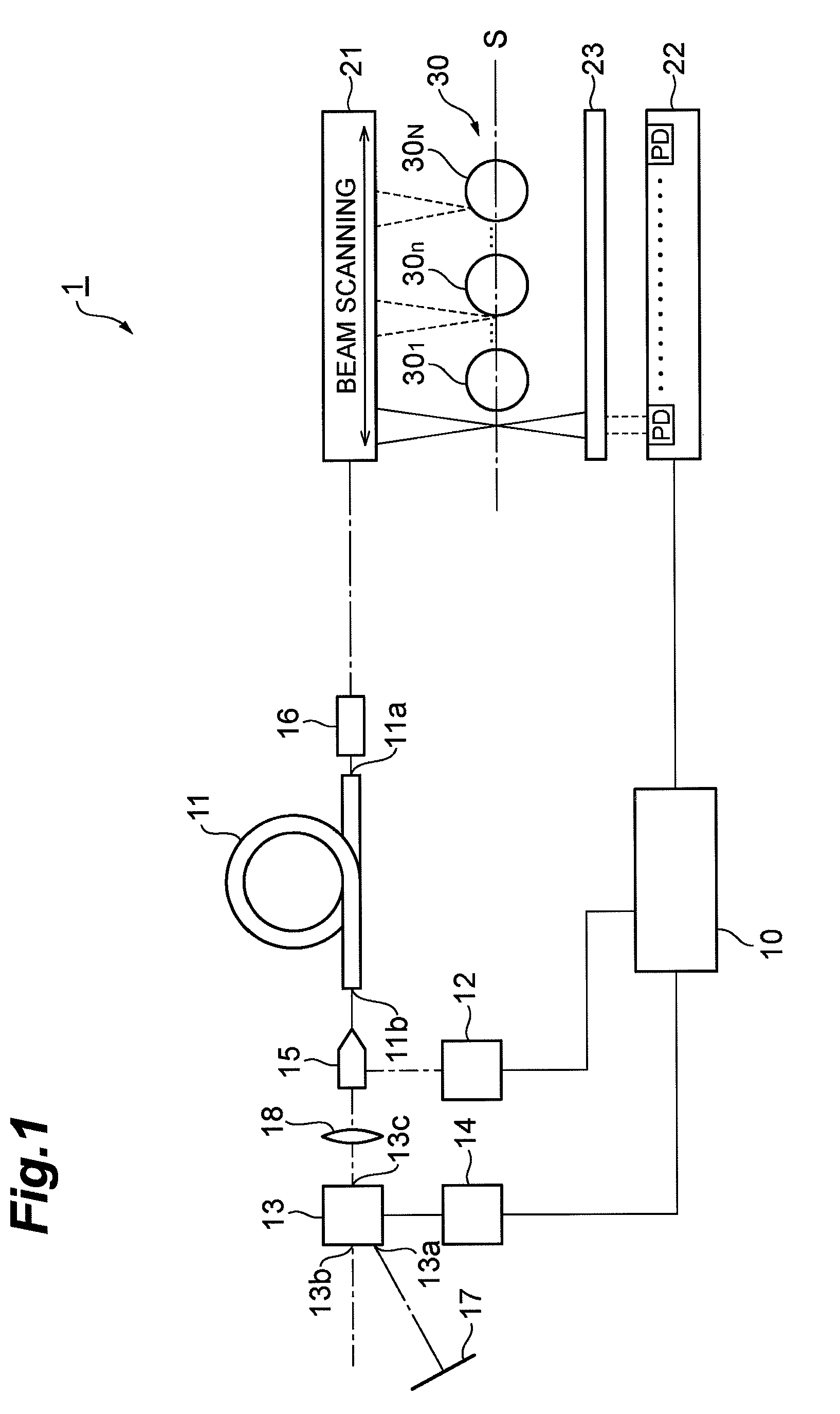
[0039]A first embodiment of a laser processing apparatus according to the present invention will be described. FIG. 1 is a view showing construction of a laser processing apparatus according to the first embodiment. A laser processing apparatus 1 according to the first embodiment shown in FIG. 1 is provided with a control section 10, an optical amplification fiber 11, an excitation light source 12, an optical switch 13, a drive circuit 14, a combiner 15, a collimator 16, a total reflection mirror 17, a lens 18, a light irradiation section 21, a photo-detector section 22 and an optical attenuation filter 23.

[0040]The optical amplification fiber 11 is an optical fiber to which optical waveguide region a fluorescent element is added. The optical amplification fiber 11, when supplied with an excitation light of a wavelength that can excite this fluorescent element, emits fluorescence from this fluorescent element. This fluorescent element is preferably a rare-earth ele...

second embodiment

A Second Embodiment

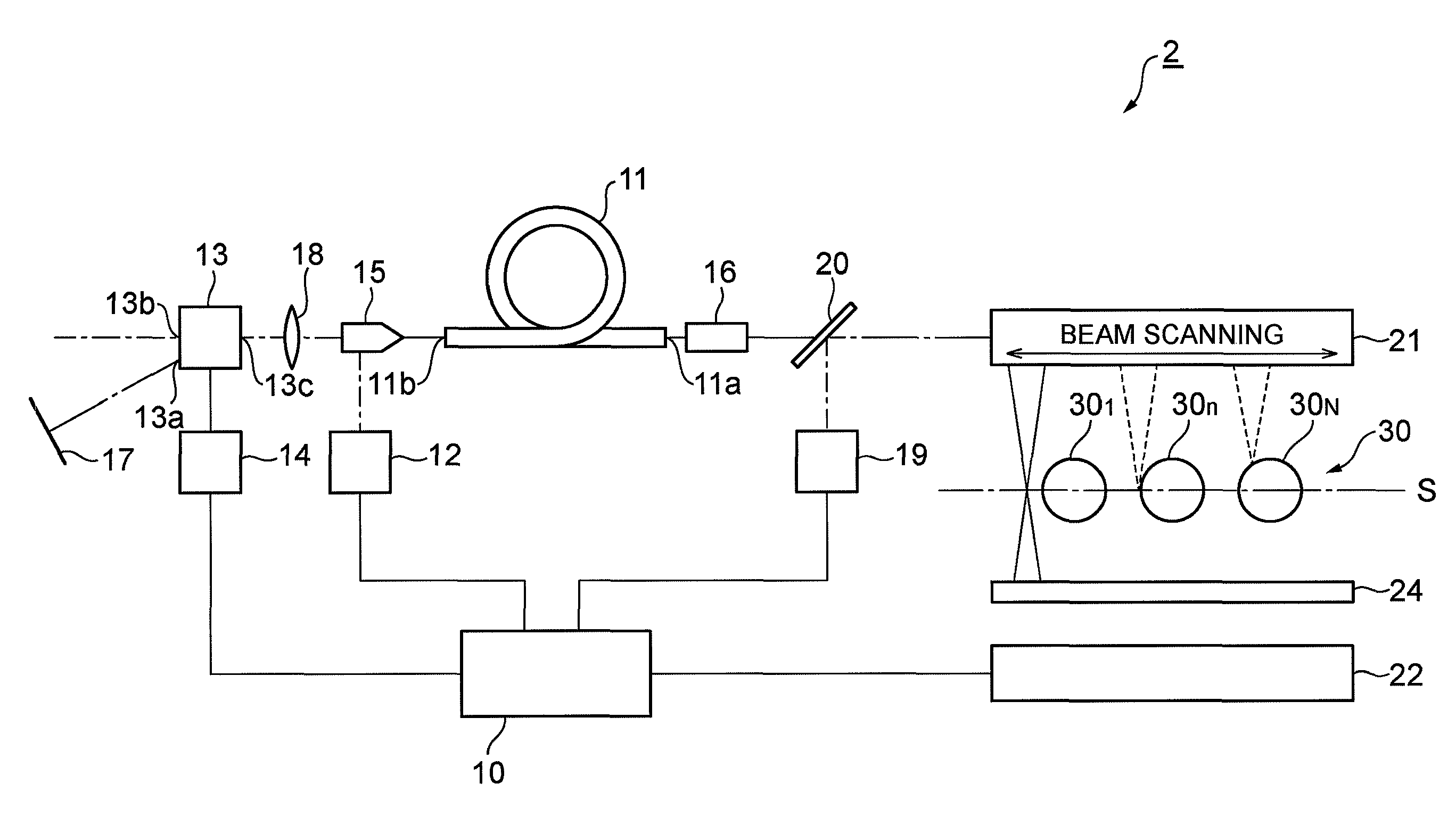
[0070]A second exemplary embodiment of a laser processing apparatus according to the present invention will be described. FIG. 6 is a view showing construction of the laser processing apparatus according to the second embodiment. The laser processing apparatus 2 according to the second embodiment shown in this FIG. 6, is provided with a control section 10, an optical amplification fiber 11, an excitation light source 12, an optical switch 13, a drive circuit 14, a combiner 15, a collimator 16, a total reflection mirror 17, a lens 18, a monitor light source 19, a dichroic mirror 20, a light irradiation section 21, a photo-detector section 22 and a spectral filter 24. The laser processing apparatus 2 according to this second embodiment is different from the laser processing apparatus 1 according to the first embodiment in the point of further provision of the monitor light source 19 and the dichroic mirror 20. Further, the laser processing apparatus 2 according to t...

embodiment

Modifications of Embodiment

[0081]In addition to the above-mentioned first and second embodiments, as the method of efficiently processing the side face of the object 30n, there is the method of changing a pulse pattern while this object 30n is being pulse-irradiated with a laser beam. Hereinafter, an example of changing the pulse pattern will be described. These modifications are useful in the case of no occurrence of overshoot on the occasion when the pulse oscillation of a laser beam is started. In specific, for example, it is MOPA arrangement, and given is e.g., the case of adopting the method in which a seed light source output is made the same as a peak value at the time of pulse oscillation even at the time when the pulse oscillation is stopped to be in the state of CW (continuous wave).

[0082]FIGS. 9A to 9C are charts for explaining examples of changing the pulse pattern of the laser beam. In particular, FIG. 9A shows the sectional view of the object 30n. FIG. 9B shows an exam...


PUM

PropertyMeasurementUnit
speedaaaaaaaaaa
scanning speedaaaaaaaaaa
optical densityaaaaaaaaaa

Abstract

The present invention relates to a laser processing apparatus and the like having a structure for implementing at the same time both an efficient laser processing in the place where a laser beam is difficult to reach and a laser processing without damages in the place where the laser beam is easy to reach. This laser processing apparatus comprises a laser light source, an irradiation optical system applying a laser beam to an object while scanning the laser beam, a photo-detector detecting the laser beam applied from the irradiation optical system, and a control section of making switching between a continuous oscillation and a pulse oscillation of the laser beam at the laser light source. In particular, the control section makes a continuous oscillation of the laser beam with respect to the laser light source in the case in which the laser beam applied from the irradiation optical system is detected at the photo-detector; while it makes a pulse oscillation of the laser beam with respect to the laser light source in the case in which no laser beam applied from the irradiation optical system is detected at the photo-detector.

Description

BACKGROUND OF THE INVENTION[0001]1. Field of the Invention[0002]The present invention relates to a laser processing apparatus and a laser processing method.[0003]2. Related Background Art[0004]By applying a laser beam with respect to the surface of an object to be processed, this irradiated portion on the surface of this object can be processed. As such a laser processing technique, for example, methods as described in the following Patent Document 1 and Patent Document 2 are disclosed.[0005][Patent Document 1] Japanese Patent Application Laid-Open No. 06-055281[0006][Patent Document 2] Japanese Patent Application Laid-Open No. 08-186918SUMMARY OF THE INVENTION[0007]The present inventors have examined the above conventional laser processing methods, and as a result, have discovered the following problems.[0008]That is, in the case in which an object to be laser-processed has an irregular shape, it is known that processing in the place where a laser beam is less likely to reach, such...

Claims


Application Information

Patent Timeline
Patent Type & Authority Patents(United States)
IPC IPC(8): G01J1/32B23K26/082B23K26/00B23K101/36
CPCB23K26/03B23K26/082B23K2101/32B23K2101/36
Inventor KAKUI, MOTOKINAKAMAE, KAZUOTAMAOKI, SHINOBU
Owner SUMITOMO ELECTRIC IND LTD
Learn More