
Laser processing apparatus

a technology of laser processing and processing equipment, which is applied in the direction of laser beam welding equipment, manufacturing tools, welding/soldering/cutting articles, etc., can solve the problem of inefficiency in processing wafers, and achieve the effect of efficient laser processing of wafers

Active Publication Date: 2020-07-21
DISCO CORP
View PDF3 Cites 0 Cited by
  • Summary
  • Abstract
  • Description
  • Claims
  • Application Information

AI Technical Summary

Benefits of technology

[0005]Accordingly, it is an object of the present invention to provide a laser processing apparatus capable of efficient processing of a workpiece including a wafer.
[0007]According to the laser processing apparatus of the present invention, the inertial force attendant on the reciprocating movement is reduced to ¼ times that in the case of the conventional moving base formed from stainless steel. For example, while the moving velocity at the time of putting the conventional moving base into high-velocity movement within a range limited by the size, of the apparatus is 1,000 mm / second at maximum, the moving velocity in the case of the moving base in the present invention can be raised to 2,000 mm / second, or approximately two times that in the conventional case. For this reason, it is possible, according to the present invention, to laser process the wafer efficiently.

Problems solved by technology

Therefore, there is a problem that high-velocity movement of the chuck table is restricted by the inertial force at the time of reciprocating the moving base in relation to the laser beam applying means, so that it is impossible to process the wafer efficiently.

Method used


Image

  • Laser processing apparatus
  • Laser processing apparatus
  • Laser processing apparatus

Examples


Embodiment Construction

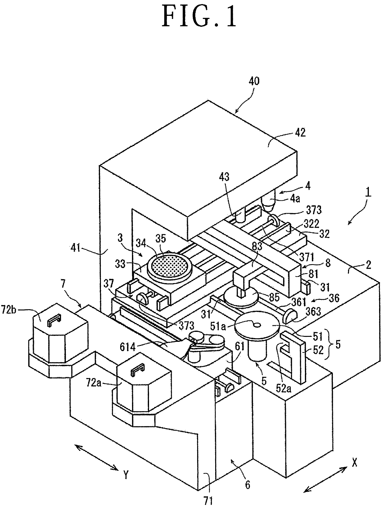
[0019]A preferable embodiment of a laser processing apparatus configured according to the present invention will be described in detail below, referring to the attached drawings. FIG. 1 depicts a perspective view of one embodiment of the laser processing apparatus configured according to the present invention. The laser processing apparatus 1 in the embodiment illustrated includes a stationary base 2, a holding table mechanism 3 which is disposed on the stationary base 2 and holds a workpiece, and laser beam applying means 4 for applying laser processing to the workpiece held by the holding table mechanism 3.

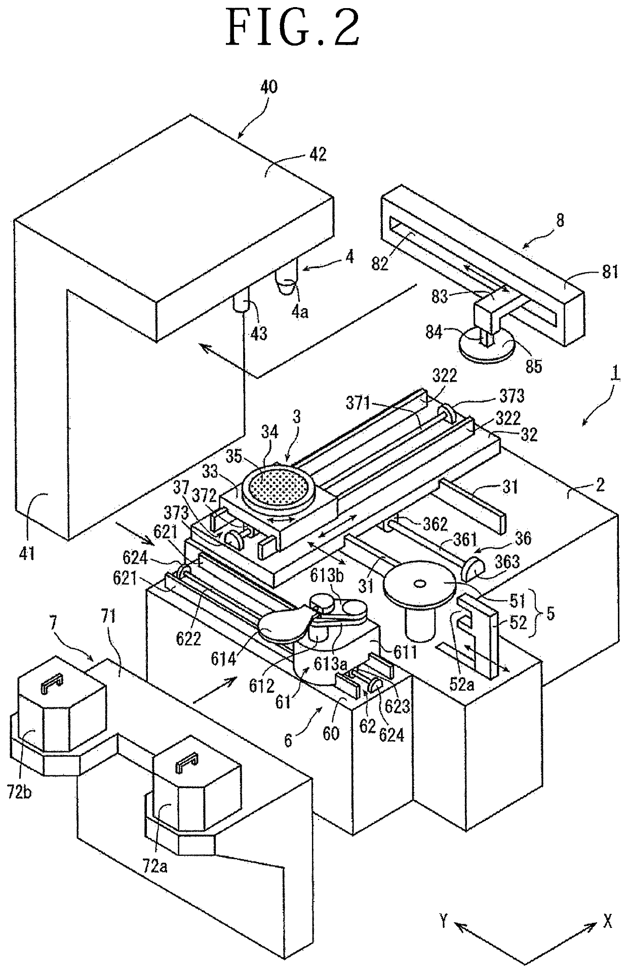
[0020]Main components of the laser processing apparatus 1 described in FIG. 1 will be described while referring to FIG. 2 which separately illustrates the main components. The holding table mechanism 3 includes a pair of Y-axis guide rails 31 disposed on the stationary base 2 in parallel to each other along a Y-axis direction indicated by arrow Y, an X-axis table 32 disposed on ...


PUM

PropertyMeasurementUnit
specific gravityaaaaaaaaaa
velocityaaaaaaaaaa
velocityaaaaaaaaaa

Abstract

A laser processing apparatus includes a cassette table for placing thereon a cassette in which a plurality of workpieces are accommodated, a carrying-out unit for carrying out the workpiece from the cassette placed on the cassette table, an X-axis direction moving unit for processing feed of a chuck table in the X-axis direction, a Y-axis direction moving unit for indexing feed of the chuck table in a Y-axis direction orthogonal to the X-axis direction, and a laser beam applying unit having a focusing unit for applying a laser beam to the workpiece held on the chuck table.

Description

BACKGROUND OF THE INVENTIONField of the Invention[0001]The present invention relates to a laser processing apparatus which is capable of efficiently processing a plate-shaped workpiece such as a wafer, thereby enhancing productivity.Description of the Related Art[0002]A wafer formed with devices such as integrated circuits (ICs) or large scale integrations (LSIs) on a front surface thereof partitioned by division lines is processed along the division lines by a laser processing apparatus, and is divided into individual device chips, which are used for electrical apparatuses such as personal computers, mobile phones, and television sets.[0003]As the laser processing apparatus, there has been known one that includes, at least, a cassette table for placing thereon a cassette in which a plurality of workpieces are accommodated, carrying-out means for carrying out the wafer from the cassette placed on the cassette table, temporary placing means for temporarily placing the wafer carried o...

Claims


Application Information

Patent Timeline
Patent Type & Authority Patents(United States)
IPC IPC(8): B23K26/08B23K26/073H01L21/78B23K26/40B23K26/18B23K26/364H01L21/67B23K26/0622B23K103/00
CPCH01L21/78B23K26/18B23K26/0884B23K26/364B23K26/40B23K26/0622B23K26/0853B23K26/0736H01L21/67132B23K2103/56B23K2103/50B23K26/702H01L21/67092H01L21/67766B23K26/38H01L21/67706H01L21/67259
Inventor NOMURA, HIROSHI
Owner DISCO CORP
Learn More