Braking device having a device spring

A brake device and brake system technology, applied in the direction of brake transmission device, fluid pressure actuation device, brake, etc., can solve the problems of increased manufacturing, assembly, sealing and calibration costs, increased weight, increased space requirements, etc. Achieve the effects of enlarged measurement range, simple connection and high measurement accuracy

Active Publication Date: 2014-12-10
CONTINENTAL AUTOMOTIVE TECH GMBH
View PDF7 Cites 2 Cited by
  • Summary
  • Abstract
  • Description
  • Claims
  • Application Information

AI Technical Summary

Problems solved by technology

[0004] The complex construction of such equipment is generally considered to be in need of improvement in terms of the required measurement accuracy and durability, in addition to increased manufacturing, assembly, sealing and calibration costs
Furthermore, this known measuring device tends to require an increased space requirement for the larger required measuring range and causes an increase in weight

Method used


Image

  • Braking device having a device spring
  • Braking device having a device spring
  • Braking device having a device spring

Examples


Embodiment Construction

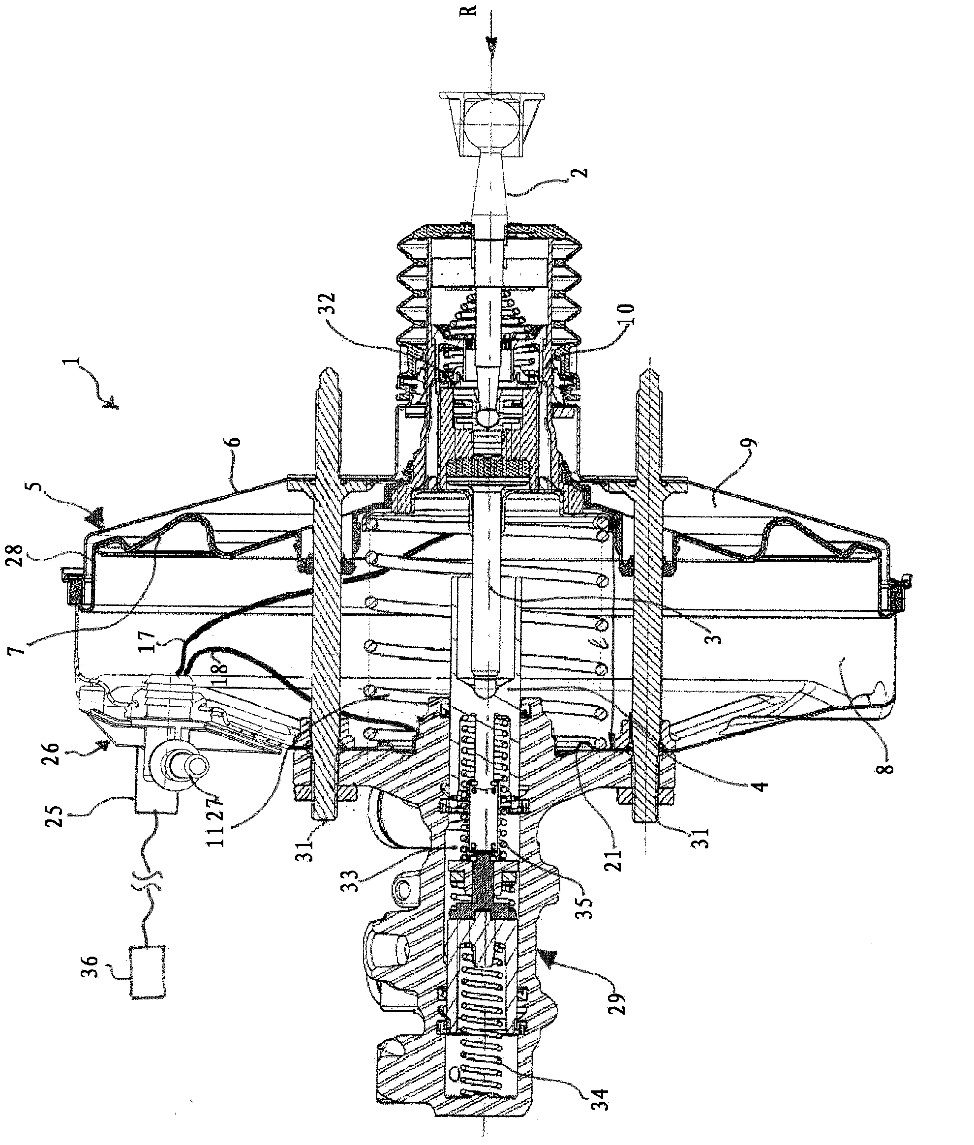
[0032] Because the principle structure and working principle of the main components of the hydraulic brake system, such as the pneumatic brake booster or the brake master cylinder, are sufficiently known, a complete detailed explanation thereof is omitted below, and only emphasis is placed on the Invent important features and relationships.

[0033] figure 1

[0034] exist figure 1 A first embodiment of a braking device 1 according to the invention is shown in . The exemplary embodiment shown includes a brake master cylinder 29 which is designed as a so-called tandem master cylinder in the form of a plunger and is fastened to the pneumatic brake booster 5 by means of tension screws 31 . Of course, other embodiments of the brake master cylinder, of a manually or externally actuatable pneumatic, hydraulic or electrohydraulic brake booster and of the fastening means are also possible within the scope of the present invention.

[0035]The brake booster 5 comprises a booster ho...


PUM


Abstract

The invention relates to a braking device (1), in particular for a motor vehicle brake system, wherein the braking device (1) has at least one movable activation element (2,3,4) and at least one device for monitoring the position and movement of at least one activation element (2, 3, 4), and at least one compressible, electrically conductive device spring (11) which is arranged in an elastically prestressed fashion between two abutments, wherein at least one of the abutments is of movable design, and the movement of the abutment is coupled at least partially to a movement of at least one activation element (2, 3 ,4), and wherein the device spring (11) is provided for moving at least one of the abutments into its unactivated release position. In order to provide an improved braking device which permits, in a cost-effective way, precise, reliable, robust and durable determination of the position and movement of an activation element, as far as possible over its entire movement range, the invention proposes that the device spring (11) be additionally assigned a sensing function in that the device spring (11) is the component of the device for monitoring the position and movement of at least one activation element (2, 3, 4), wherein a degree of compression of the device spring (11) can be sensed, and wherein the device spring (11) is arranged in an electrically insulated fashion between the two abutments.

Description

technical field [0001] The invention relates to a braking device, in particular for a motor vehicle braking system, having the features stated in the preamble of independent claim 1 . Background technique [0002] It is important and necessary for a motor vehicle braking system to be able to know as accurately as possible the state of the system at any given moment, in particular the position of the actuating components which is relevant for the build-up of the brake pressure. In motor vehicle brake systems with a pneumatic brake booster, for example, the instantaneous position of a movable wall within the brake booster coupled with respect to its position and movement to the actuating element can be used as a measure of the system state. The obtained information may be transmitted in the form of electrical signals to a control unit, a brake light switch or other devices. A separate measuring device is used for this. [0003] A pneumatic brake booster with a sensor device ...

Claims


Application Information

Patent Timeline
Patent Type & Authority Applications(China)
IPC IPC(8): B60T13/52B60T17/22G01L1/14B60Q1/44F15B15/28G01D5/20G01B7/02
CPCB60T13/569B60T17/22B60T13/52
Inventor J·法勒
Owner CONTINENTAL AUTOMOTIVE TECH GMBH
Why Eureka
Try Eureka