Yarn monitoring method

A technology for yarn and yarn quality, applied in the field of yarn extraction units, can solve the problems of time-consuming, defects, and yarn quality that does not meet the requirements, and achieve the effect of simplifying the selection process

Inactive Publication Date: 2014-12-10
MASCHINENFABRIK RIETER AG
View PDF7 Cites 5 Cited by
  • Summary
  • Abstract
  • Description
  • Claims
  • Application Information

AI Technical Summary

Problems solved by technology

[0005] However, the above approach is disadvantageous in the state of the art, because the initial reference value determination process is time-consuming and flawed
Especially when the initial reference value determination process is wrong for some reason, so that the quality of the entire batch of yarn will not meet the specifications

Method used


Image

  • Yarn monitoring method
  • Yarn monitoring method
  • Yarn monitoring method

Examples


Embodiment Construction

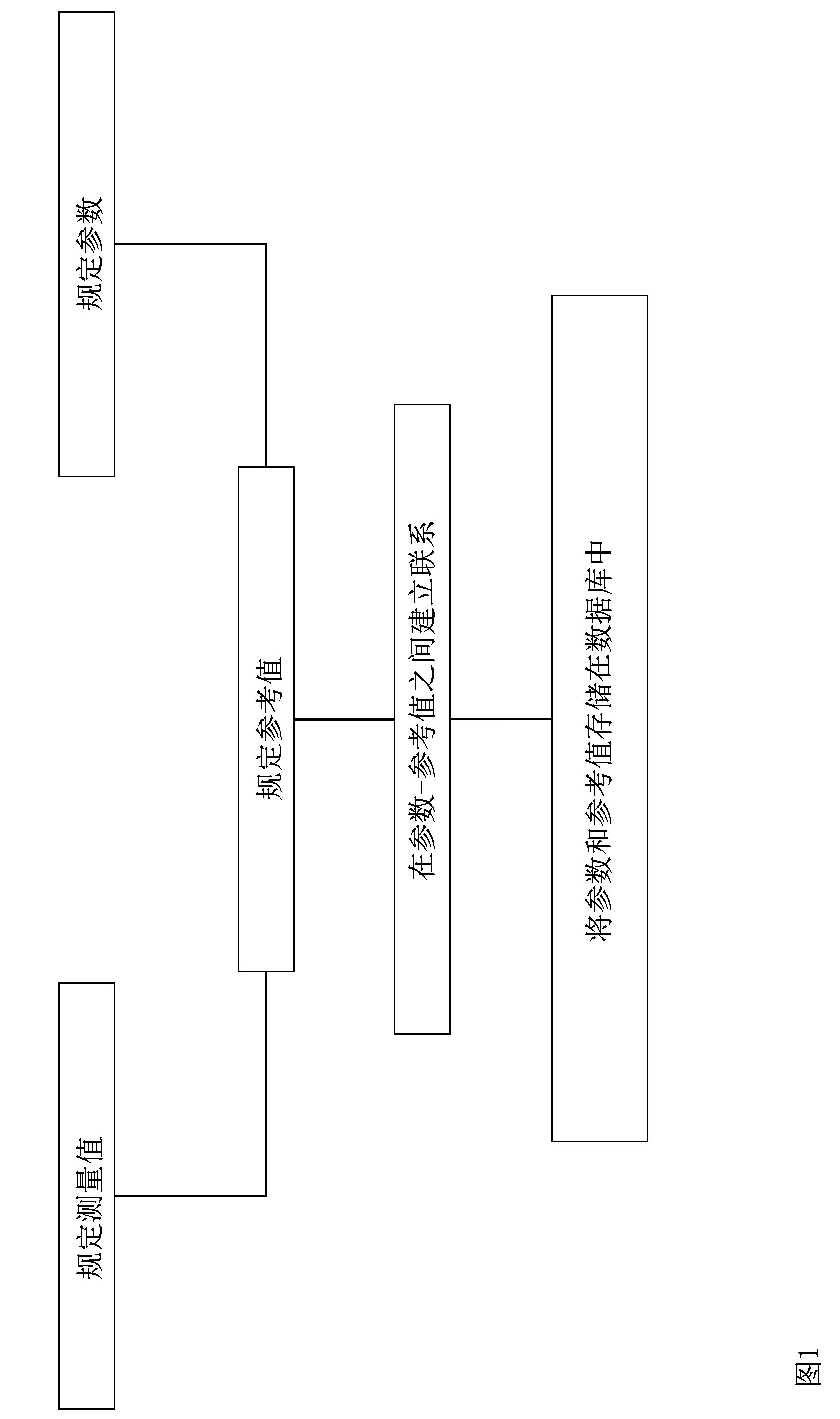
[0030] figure 1 The process of obtaining the required reference value according to the method of the present invention and storing it in the database is described in the form of a chart.

[0031] First, the measured value is defined, which is later collected and used as the basis for quality assessment when monitoring the yarn quality on the textile machine. For example, a current signal generated by a camera can be used as the measured value, and the camera can determine the geometry, in particular the width, of the projection produced by the yarn when it is illuminated by light. In this case the value of the measured value depends on the yarn thickness (=spatial extent perpendicular to the longitudinal axis of the yarn), ie the yarn thickness is monitored.

[0032] After specifying the measured value, a reference value is defined for the measured value. The reference value is the value that the measured value should have when the yarn quality is intact. Of course, as a su...


PUM


Abstract

The invention relates to a method for monitoring the quality of a yarn on a textile machine, wherein the yarn passes a monitoring unit of the textile machine, with the aid of which at least one measured variable (M) which is dependent on a physical parameter of the yarn is determined, and wherein the measured variable (M), or a variable derived therefrom, is evaluated with respect to the position thereof with regard to at least one reference value (R). According to the invention, it is proposed that the selection of the reference value(s) (R) takes place taking into account one or more characteristic variables of the yarn, said characteristic variables being yarn-specific and defined prior to evaluating the measured variable (M). Furthermore, a textile machine is proposed which comprises at least one monitoring unit for monitoring at least one physical parameter of the yarn, and at least one controller which is operatively connected to the monitoring unit. The textile machine is characterized in that the controller is configured to monitor the yarn quality according to one or more of the preceding claims.

Description

technical field [0001] The invention relates to a yarn drawing unit of a rotor spinning machine, which includes a yarn drawing nozzle extending into the spinning chamber of the rotor spinning machine, and a drawing nozzle for drawing out the yarn generated in the spinning chamber. A yarn bobbin, wherein, in the yarn-drawing direction of the yarn drawn out from the spinning chamber, the yarn-drawing bobbin is installed at a position downstream of the yarn-drawing nozzle. Furthermore, the invention relates to a method for producing yarn by means of a rotor spinning machine, in which a fiber material consisting of individual fibers is twisted to form a yarn by means of a spinning rotor in the spinning chamber of a spinning position , Then, the yarn can be drawn out from the spinning chamber by means of the yarn delivery nozzle and via the yarn delivery tube. Finally, the invention also describes a yarn delivery nozzle for use in a rotor spinning machine, which is equipped with a...

Claims


Application Information

Patent Timeline
Patent Type & Authority Applications(China)
IPC IPC(8): B65H63/06G01N33/36
CPCB65H2701/31B65H63/06G01N33/365
Inventor M·布尔歇特V·杰勒
Owner MASCHINENFABRIK RIETER AG
Why Eureka
Try Eureka