Method for dynamically measuring width of steel billet by using laser displacement sensors

A technology of laser displacement and sensors, which is applied in the direction of measuring devices, optical devices, instruments, etc., can solve problems such as huge investment, low cost performance, and complicated technology

Active Publication Date: 2014-12-17
XINXING DUCTILE IRON PIPES XINJIANG
View PDF6 Cites 11 Cited by
  • Summary
  • Abstract
  • Description
  • Claims
  • Application Information

AI Technical Summary

Problems solved by technology

[0002] The real-time measurement method of billet width applied by optical width measuring equipment generally adopts CCD camera technology and edge detection technology. The infrared radiation generated by the hot billet can be detected by the camera, or the cold billet forms the outline through the backlight, and the light intensity varies from dark to bright. The position points of the edge show the position of the edge. The CCD camera scans the linear array of pixels in the width direction of the billet to form a series of analog brightness readings at a certain interval. Each analog brightness reading represents a pixel. These analog brightness readings are converted into digital Signal, the edge determination circuit checks the changes in the amplitude of adjacent pixels, the pixels on one side of the edge are defined as "bright areas", while the other side of the edge is defined as "dark areas", the edge position can be determined, billet The length of a straight line between two edge positions in the width direction is defined as the "width" of the billet, but the existing optical width measuring equipment is mainly used in the product processing technology industry with high requirements for dimensional precision, and the technology used is relatively complicated. The cost is high, the cost performance is low, and the investment is huge

Method used


Image

  • Method for dynamically measuring width of steel billet by using laser displacement sensors
  • Method for dynamically measuring width of steel billet by using laser displacement sensors
  • Method for dynamically measuring width of steel billet by using laser displacement sensors

Examples


Embodiment Construction

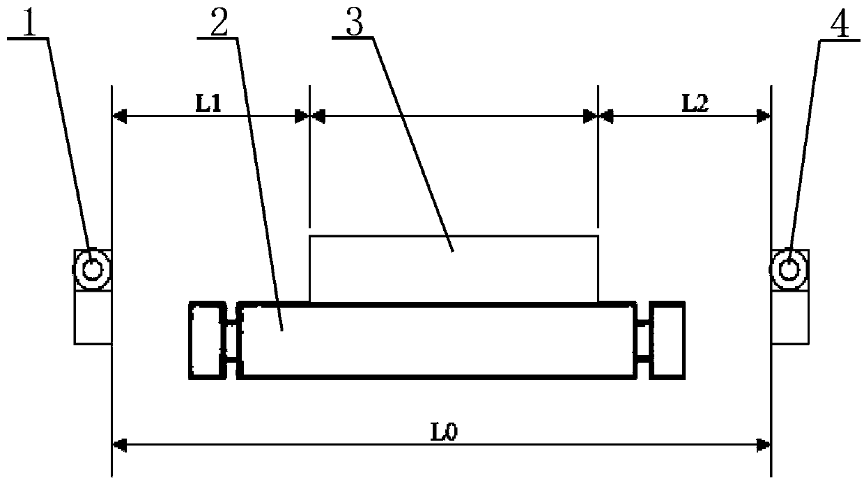
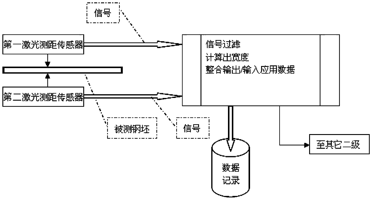
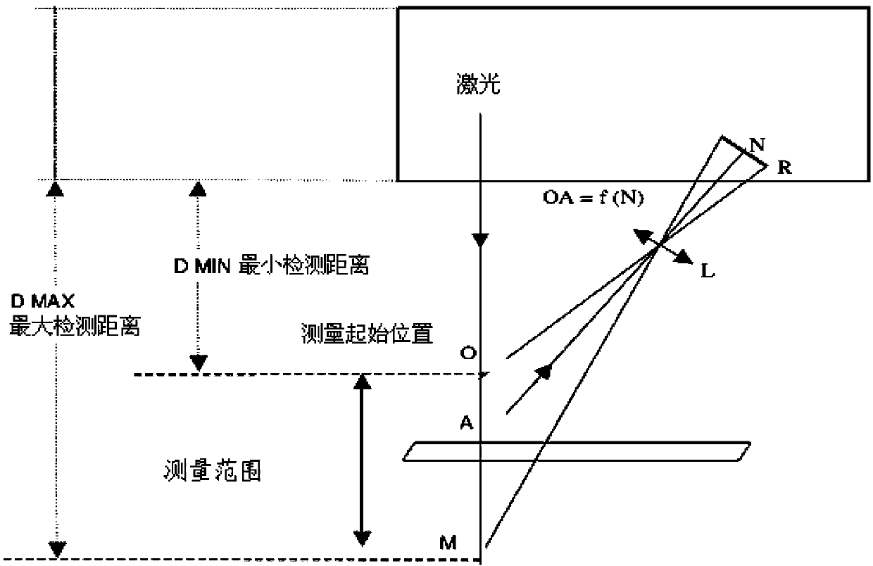
[0009] A method for dynamically measuring billet width using a laser displacement sensor such as figure 1 , figure 2 As shown, the characteristics of the method steps are: ① using an optical triangulation device including two laser displacement sensors, installing the two laser displacement sensors on both sides of the roller table 2 before the billet 3 is purged, and the two laser displacement sensors The laser emitting end of the displacement sensor faces the side wall surface of the steel billet 3, and the camera is used to shoot the steel billet 3 currently moving on the roller table 2 and the video signal captured in real time is synchronously transmitted to the industrial control computer. When the steel billet 3 passes through the two When the position between the two laser displacement sensors, the distance between the first laser displacement sensor 1 and the side of the steel billet 3 measured by the optical triangulation is L1, and the second laser displacement sen...


PUM


Abstract

The invention discloses a method for dynamically measuring width of a steel billet by using laser displacement sensors. The method includes that 1, two laser displacement sensors are mounted on two sides of a roller way respectively before the steel billet is swept, and a camera is adopted to photograph the steel billet currently moving on the roller way; 2, an industrial control computer sequentially calculates discrete width value of the current steel billet and correspondingly displays matched width curve, discrete width value and video images capable of showing the surface of the steel billet currently moving on the roller way in real time through a display screen; 3, the industrial control computer compares planed steel billet width with the discrete width value acquired by calculating the steel billet currently moving on the roller way; when width difference value acquired through subtraction of the planned steel billet width and the discrete width value exceeds a set difference value range, an optical triangular measuring device is allowed to give out sound for alarming, the discrete width value Width is enabled to be in one-to-one correspondence to corresponding billet number, planned steel billet width and mark digit to form relevant data, and the relevant data formed correspondingly in real time are stored. By the method, measuring technical means is simplified, and requirements on accuracy in actual measuring of steel billet width are met.

Description

technical field [0001] The invention relates to a size monitoring device, in particular to a method for dynamically measuring the width of a billet by using a laser displacement sensor. Background technique [0002] The real-time measurement method of billet width applied by optical width measuring equipment generally adopts CCD camera technology and edge detection technology. The infrared radiation generated by the hot billet can be detected by the camera, or the cold billet forms the outline through the backlight, and the light intensity varies from dark to bright. The position points of the edge show the position of the edge. The CCD camera scans the linear array of pixels in the width direction of the billet to form a series of analog brightness readings at a certain interval. Each analog brightness reading represents a pixel. These analog brightness readings are converted into digital Signal, the edge determination circuit checks the changes in the amplitude of adjacent...

Claims


Application Information

Patent Timeline
Patent Type & Authority Applications(China)
IPC IPC(8): G01B11/02
Inventor 朱秋峰
Owner XINXING DUCTILE IRON PIPES XINJIANG
Why Eureka
Try Eureka