
Optical socket and optical module with such optical socket

An optical socket and optical fiber technology, applied in the coupling of optical waveguides, light guides, optics, etc., can solve the problems of reduced optical information transmission efficiency, poor coupling efficiency, inability to improve the installation strength of the photoelectric conversion device 8, etc., and achieve excellent optical characteristics. Effect

Inactive Publication Date: 2017-11-28
ENPLAS CORP
View PDF8 Cites 0 Cited by
  • Summary
  • Abstract
  • Description
  • Claims
  • Application Information

AI Technical Summary

Problems solved by technology

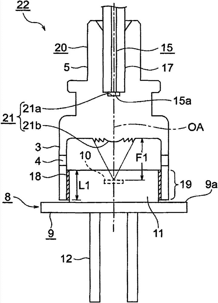
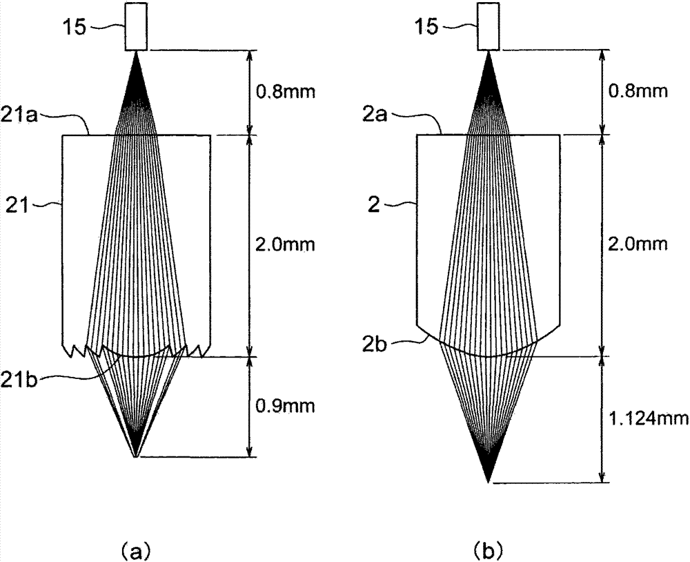
However, since the second surface 2b of the lens 2 is a convex surface, the focal distance F2 to the position where the light emitted to the downstream side is collected is long, so when the light receiving element 10 of the photoelectric conversion device 8 and the position of the focal distance F2 When they are arranged uniformly, the axial length L2 of the bonding gap 19 is physically shortened, and the axial length L2 cannot be increased to improve the mounting strength of the photoelectric conversion device 8 to the photoelectric conversion device mounting part 3, which may be inappropriate.
[0016] In addition, in the optical receptacle 1, the optical fiber mounting part 5 and the ferrule 17 are detachably formed with predetermined durability and compatibility, but as the number of detachment operations increases, the joint surface of the two gradually wears out, and the optical fiber 15 and the metal ferrule 17 are damaged. The optical axis of the ferrule 17 is tilted with respect to the optical axes of the optical fiber mounting part 5, the lens 2, and the photoelectric conversion device 8 on their downstream side.
[0017] When this shaking occurs, the optical axis of the optical fiber 15 is inclined to the optical axis of the lens 2, and the light emitted from the end face 15a of the optical fiber 15, the light on the optical axis and the light diffused from the optical axis due to the light-gathering characteristics of the lens 2 However, the light that diffuses greatly from the optical axis cannot be collected on the optical axis of the light receiving element 10 even by utilizing the light-condensing characteristics of the lens 2 formed in a plano-convex shape. In this state, the coupling efficiency deteriorates and the transmission efficiency of optical information decreases.

Method used


Image

  • Optical socket and optical module with such optical socket
  • Optical socket and optical module with such optical socket
  • Optical socket and optical module with such optical socket

Examples


Embodiment Construction

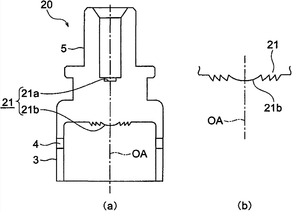
[0036] Below, refer to Figure 1 to Figure 5 Embodiments of the present invention will be described.

[0037] However, where the basic structure is the same as or similar to that of the prior art, the same symbols are used for description.

[0038] Such as figure 1 as well as figure 2As shown, optical receptacle 20 in this embodiment is configured by integrally forming lens 21 , photoelectric conversion device mounting portion 3 , and optical fiber mounting portion 5 using a translucent resin material like conventional optical receptacle 1 . In addition, the optical receptacle 20 in this embodiment is different from the conventional example in that the lens 21 is formed as a Fresnel lens having a convex surface on the second surface 21 b facing the light receiving element 10 .

[0039] For further clarification, in Figure 6 In the existing structure shown in , the lens 2 is formed on the upstream side of the light in the direction of its optical axis OA ( Figure 6 The f...


PUM


Abstract

An optical receptacle includes a cylindrical optical fiber attaching section for attaching an end portion of an optical fiber by insertion; a cylindrical photoelectric conversion device attaching section that includes an inner circumferential surface into which a photoelectric conversion device having a light-receiving element is inserted and for attaching the photoelectric conversion device with an adhesive that is interposed within an annular adhesion space; and a lens for optically coupling the end portion of the optical fiber and the light-emitting element, and the lens is a Fresnel lens in which a second face that faces the light-receiving element includes a convex face.

Description

technical field [0001] The present invention relates to an optical receptacle and an optical module having such an optical receptacle, in particular to an optical receptacle suitable for coupling the end of an optical fiber and a light receiving element of a photoelectric conversion device with excellent optical characteristics and an optical module having such an optical receptacle. Background technique [0002] Conventionally, in optical communication using an optical fiber, an optical module part called an optical receptacle is used. The optical receptacle can insert and fix the end of the optical fiber held in a cylindrical ferrule together with the ferrule, and the installation has A photoelectric conversion device of a photoelectric conversion element. In addition, the optical receptacle in which the photoelectric conversion device and the optical fiber are assembled in this way optically couples the photoelectric conversion device and the end of the optical fiber. ...

Claims


Application Information

Patent Timeline
Patent Type & Authority Patents(China)
IPC IPC(8): G02B6/42
CPCG02B6/4204G02B6/4206G02B6/4292
Inventor 涩谷和孝
Owner ENPLAS CORP
Learn More