
Shielding shell and framework structure and transformer with shielding shell and framework structure

A technology of skeleton structure and shielding shell, which is applied in the parts of transformer/inductor, transformer/inductor coil/winding/connection, preventing/reducing unwanted electric/magnetic influence, etc., and can solve the problems affecting the shielding effect, etc.

Active Publication Date: 2022-01-28
JIANGSU EASTONE TECH
View PDF5 Cites 0 Cited by
  • Summary
  • Abstract
  • Description
  • Claims
  • Application Information

AI Technical Summary

Problems solved by technology

[0005] One of the purposes of the present invention is to solve the problem that the inductor or transformer structure in the prior art can affect the shielding effect

Method used


Image

  • Shielding shell and framework structure and transformer with shielding shell and framework structure
  • Shielding shell and framework structure and transformer with shielding shell and framework structure
  • Shielding shell and framework structure and transformer with shielding shell and framework structure

Examples


Embodiment 1

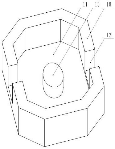
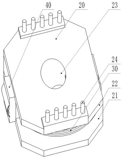
[0037] A shielding shell and skeleton structure, such as Figure 2-6 As shown, it includes: shielding shell 10, winding frame 20, coil 30 and shielding plate 50, such as image 3 , 4As shown, the coil 30 is wound in the wire groove 21 of the winding frame 20, and the holding piece 40 made of magnetic material is embedded in the flange 22 of the winding frame 20, and the outer surface of the holding piece 40 is provided with side through holes 41 on both sides. The inner surface of the sheet 40 is provided with a communication opening 42 communicating with the side through hole 41 , and the communication opening 42 is communicating with the wire groove 21 .

[0038] The specific shape of the holding piece 40 is "匚" shape or square plate shape, and the flange 22 of the winding frame 20 is provided with a gap that cooperates with the holding piece 40, specifically, the holding piece 40 is snapped into the gap to realize The holding piece 40 is embedded in the operation of the f...

Embodiment 2

[0054] A transformer, which has the shielding shell and skeleton structure in the first embodiment.

Embodiment 3

[0056] A painting method, applied to the shielding shell and skeleton structure in the first embodiment above or the transformer in the second embodiment, wherein the painting method includes the following steps:

[0057] The shielding shell and the frame structure are immersed in the insulating varnish, and the insulating varnish enters the communication port 42 along the side through holes 41 on both sides of the holding piece 40, and the insulating varnish passing through the communication port 42 is divided into two paths.

[0058] One path of insulating varnish flows into the wire slot 21 of the winding frame 20 through the communication port 42, and paints the outer surface of the coil 30 in the wire slot 21; , the insulating varnish that enters the channel 44 enters the inner surface of the coil 30 to be painted along the diversion groove 45, and the inner and outer surfaces of the coil 30 are infiltrated by the two-way insulating varnish, so that the inner and outer sur...


PUM


Abstract

The invention discloses a shielding shell and framework structure and a transformer with the shielding shell and framework structure, and relates to the technical field of power equipment. The shielding shell and framework structure comprises a shielding shell, a winding framework, a coil and a shielding plate; the coil is wound on a wire slot of the winding framework; and a central hole of the winding framework is aligned with a magnetic column sheathed in the shielding shell. A closed window of the shielding shell in the prior art is designed into a semi-closed opening, a holding piece matched with the semi-closed opening is added on the basis of the winding framework, and after the holding piece is embedded into the semi-closed opening of the shielding shell, the accommodating cavity of the shielding shell forms a basically complete surrounding structure. On one hand, the shielding shell can better surround the coil and the winding framework, and the shielding effect of the shielding shell is enhanced; and on the other hand, a side through hole, a communication openings and a channel structure formed in the holding piece are conveniently utilized, so that insulating paint is shunted to paint the inner and outer surfaces of the coil during paint dipping, and the insulating effect of the coil is improved.

Description

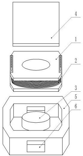
technical field [0001] The invention relates to the technical field of electric equipment, in particular to a shielding case and a skeleton structure. Background technique [0002] As common components in power equipment, inductors and transformers are favored by many businesses. Such as figure 1 The disclosed inductor or transformer structure. [0003] The inductor or transformer structure includes a bobbin 1 and a magnetic part 3 wound with a winding coil 2, and the upper side plate 4 and the housing 5 surround the bobbin 1 and the magnetic part 3 to shield or reduce the inductor or The magnetic field generated by the transformer affects the work of other power components. [0004] However, in the varnish dipping process of the inductor or transformer, the insulating varnish enters the structure of the inductor or transformer through the window 6 of the housing 5, and the insulating varnish will coat the outer surface of the winding frame 1 and the winding group coil 2....

Claims


Application Information

Patent Timeline
Patent Type & Authority Applications(China)
IPC IPC(8): H01F27/30H01F27/32H01F27/36
CPCH01F27/306H01F27/36H01F27/324H01F27/323
Inventor 卢卫国刘扬许勇
Owner JIANGSU EASTONE TECH
Learn More